
High-speed raw material dispersion mixer for paint production

A high-speed dispersion and mixer technology, applied to mixers with rotating stirring devices, mixers, mixing methods, etc., can solve problems such as poor mixing and dispersing effects, prolonged coating processing time, and inability to achieve synchronization in raw material mixing. Good mixing purpose, good mixing uniformity effect

Inactive Publication Date: 2018-03-09
丹阳市海信涂料化工厂
View PDF3 Cites 3 Cited by
  • Summary
  • Abstract
  • Description
  • Claims
  • Application Information

AI Technical Summary

Problems solved by technology

[0003] Coating production steps mainly include raw material pre-dispersion - grinding and dispersing - coating adjustment - filtering and packaging, etc., and the uniformity of coating mixing is the fundamental guarantee of coating quality. Most of the existing technologies are distributed according to the above steps, according to each Step down the processing time of coating can prolong, and the pre-dispersion mixing in the prior art is inhomogeneous, and its mixing and dispersing effect is poor; And because the paint is viscous, part of the paint will stick to the inner wall of the grinding and dispersing machine during the stirring process, resulting in waste of paint; again, the general stirring equipment mainly uses the high-speed stirring of the stirring shaft to complete, but the paint is in the production process. There are several kinds of raw materials, the quality of paint production is mainly reflected in the uniformity of raw material mixing, and the existing mixing and mixing equipment can not achieve the purpose of mixing several kinds of raw materials at the same time, but use one by one to add. Mixing, which will cause the mixing of raw materials to fail to achieve synchronization

Method used


Image

  • High-speed raw material dispersion mixer for paint production
  • High-speed raw material dispersion mixer for paint production

Examples


Embodiment Construction

[0019] In order to enable those skilled in the art to better understand the technical solution of the present invention, the technical solution of the present invention will be further described below in conjunction with the accompanying drawings and embodiments.

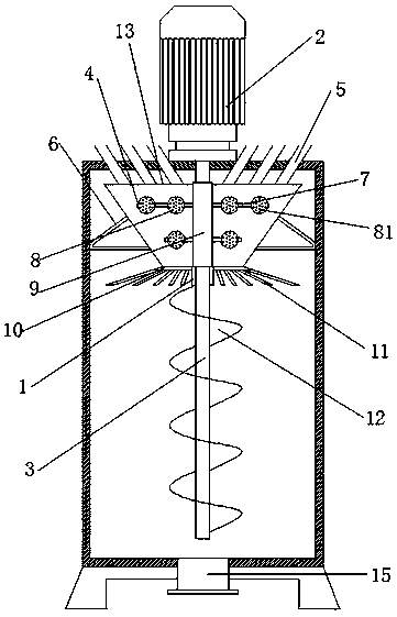
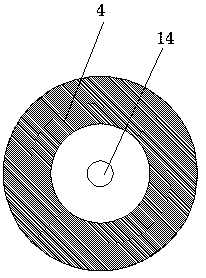
[0020] Refer to attached Figure 1-2 The shown raw material high-speed dispersing mixer for coating production includes a mixing bucket 1, a discharge port 15 is arranged below the mixing bucket 1, the mixing bucket 1 is fixedly arranged on a base, and a power mechanism is set at the top of the mixing bucket 1 2. The bottom of the drive end of the power mechanism 2 extends to the stirring shaft 3 in the mixing bucket 1. The power mechanism 2 adopts a motor, and a pre-mixing shaft separate from it is provided on the upper end of the stirring shaft 3. material mechanism, a mixing transition mechanism is arranged below the premixing mechanism, and the mixing transition mechanism is fixedly connected to the stirring sha...


PUM


Abstract

The invention discloses a high-speed raw material dispersion mixer for paint production. The dispersion mixer comprises an agitating tank, wherein a power mechanism is arranged at the top end of the agitating tank; a transmission end of the power mechanism is in transmission connection with an agitating shaft; the bottom of the agitating shaft extends into the agitating tank; a premixing mechanismseparated from the agitating shaft is arranged at the upper end of the agitating shaft; a mixing transition mechanism is arranged below the premixing mechanism and fixedly connected with the agitating shaft; the agitating shaft comprises an upper agitating part and a lower agitating part; the upper agitating part comprises at least one row of horizontal agitators; each horizontal agitator comprises a horizontal rod and a disc type agitating component; the lower agitating part is a spiral agitator; the high-speed mixer is simple in structure and low in manufacturing cost, and achieves a synchronous premixing purpose; due to a rotary blanking manner, the blanking is more uniform; a radiation angle is more complete; an agitating dead angle is avoided; and the mixer can shorten the mixing time greatly and improve the agitating efficiency.

Description

technical field [0001] The invention relates to a raw material high-speed dispersing mixer for paint production. Background technique [0002] Coating is a kind of material, which can be coated on the surface of objects by different construction techniques to form a continuous solid film with firm adhesion, certain strength, and coating belongs to fine chemical products. Modern coatings are gradually becoming a class of multi- Functional engineering materials are an important industry in the chemical industry and have been widely used in various industries. [0003] Coating production steps mainly include raw material pre-dispersion - grinding and dispersing - coating adjustment - filtration and packaging, etc., and the uniformity of coating mixing is the fundamental guarantee of coating quality. Most of the existing technologies are distributed according to the above steps, according to each Step down the processing time of coating can prolong, and the pre-dispersion mixin...

Claims


Application Information

Patent Timeline
Patent Type & Authority Applications(China)
IPC IPC(8): B01F3/20B01F7/24B01F7/26B01F15/02B01F23/70B01F27/93
CPCB01F23/70B01F27/93B01F27/92B01F35/71B01F2101/30
Inventor 黄新良
Owner 丹阳市海信涂料化工厂
Learn More