Totally-closed constant-temperature self-adjusted energy-saving transmission machine room
An energy-saving transmission and self-adjusting technology, applied in the direction of sealed enclosures, instruments, cooling/ventilation/heating renovation, etc., can solve the problems of corrosion of electrical components, large energy consumption of refrigeration equipment, etc., to achieve extended service life, high heat exchange efficiency, Stable performance
- Summary
- Abstract
- Description
- Claims
- Application Information
AI Technical Summary
Problems solved by technology
Method used
Image
Examples
Embodiment 1
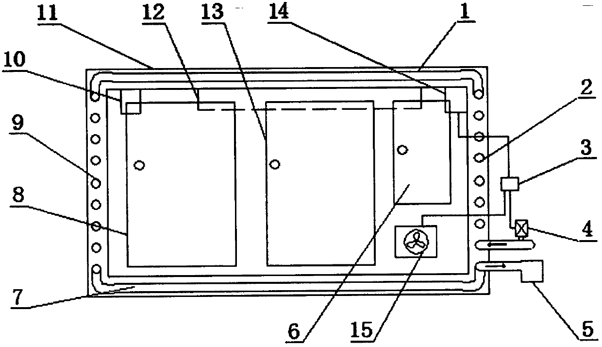
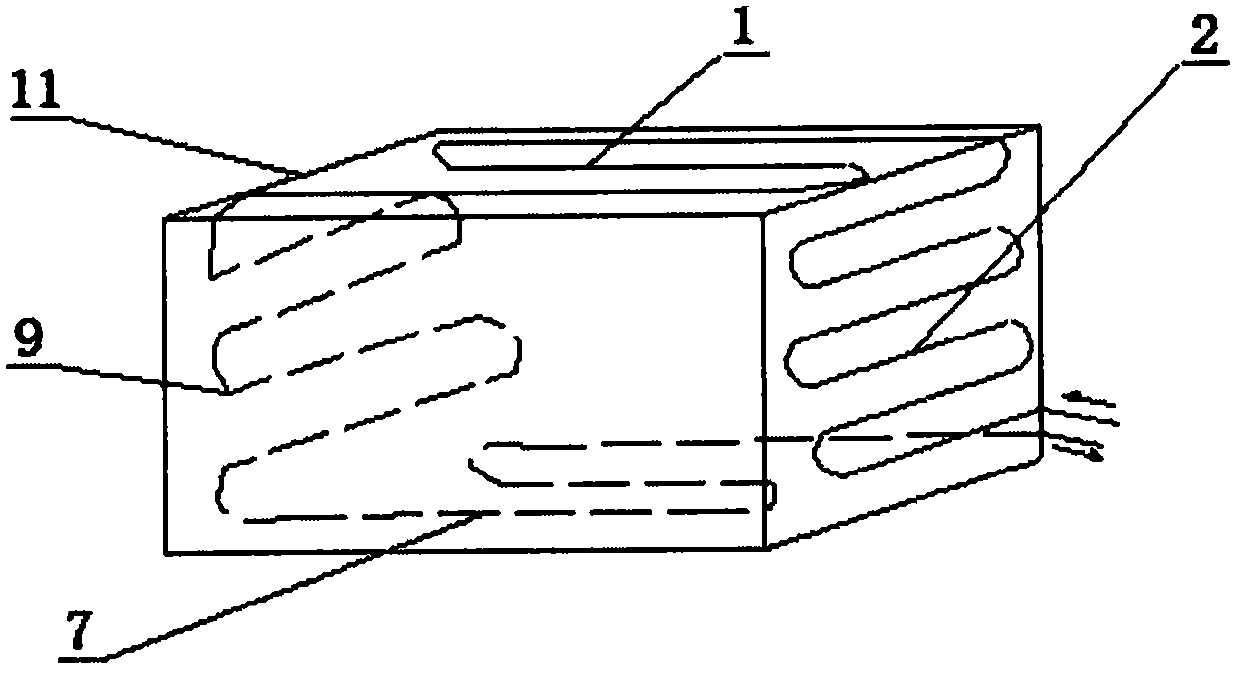
[0015] Such as figure 1 with figure 2 As shown, a fully enclosed thermostatic self-adjusting energy-saving transmission room includes a cabinet body 11, a control terminal 3 and an exhaust fan 15. The main body of the cabinet body 11 is composed of hollow thin-walled pieces. The left side of the cabinet body 11 An S heat exchange tube B2 is provided in the wall, an S heat exchange tube D9 is provided in the right side wall of the cabinet 11, an S heat exchange tube A1 is provided in the top wall of the cabinet 11, and an S heat exchange tube A1 is provided in the bottom wall of the cabinet 11 S heat exchange tube C7, the front of the cabinet 11 is provided with a sealed cabinet door B8, a sealed cabinet door C13, a sealed cabinet door A6, and an exhaust fan 15. The cabinet 11 is provided with a light smoke sensor device 10, a dehumidification device 12, and a temperature Sensor 14; the S heat exchange tube B2 is arranged in the right side wall of the cabinet 11, the S heat exc...
Embodiment 2
[0019] Such as figure 1 with figure 2 As shown, a fully enclosed thermostatic self-adjusting energy-saving transmission room includes a cabinet body 11, a control terminal 3 and an exhaust fan 15. The main body of the cabinet body 11 is composed of hollow thin-walled pieces. The left side of the cabinet body 11 An S heat exchange tube B2 is provided in the wall, an S heat exchange tube D9 is provided in the right side wall of the cabinet 11, an S heat exchange tube A1 is provided in the top wall of the cabinet 11, and an S heat exchange tube A1 is provided in the bottom wall of the cabinet 11 S heat exchange tube C7, the front of the cabinet 11 is provided with a sealed cabinet door B8, a sealed cabinet door C13, a sealed cabinet door A6, and an exhaust fan 15. The cabinet 11 is provided with a light smoke sensor device 10, a dehumidification device 12, and a temperature Sensor 14; the S heat exchange tube B2 is arranged in the right side wall of the cabinet 11, the S heat exc...
PUM
 Abstract
Description
Claims
Application Information
 - R&D Engineer
- R&D Manager
- IP Professional
- Industry Leading Data Capabilities
- Powerful AI technology
- Patent DNA Extraction
Browse by: Latest US Patents, China's latest patents, Technical Efficacy Thesaurus, Application Domain, Technology Topic, Popular Technical Reports.
© 2024 PatSnap. All rights reserved.Legal|Privacy policy|Modern Slavery Act Transparency Statement|Sitemap|About US| Contact US: help@patsnap.com


