SiC switch tube driving circuit and method of synchronous rectification Buck convertor
A synchronous rectification and drive circuit technology, applied in the direction of DC power input conversion to DC power output, instruments, electrical components, etc., can solve the problems of improving the complexity of system control and extra, achieve crosstalk, achieve suppression, and meet harsh requirements Effect
- Summary
- Abstract
- Description
- Claims
- Application Information
AI Technical Summary
Problems solved by technology
Method used
Image
Examples
Embodiment Construction
[0033] The SiC switching tube drive circuit suitable for synchronous rectification Buck converters provided by the present invention will be further described in detail below with reference to the accompanying drawings and examples.
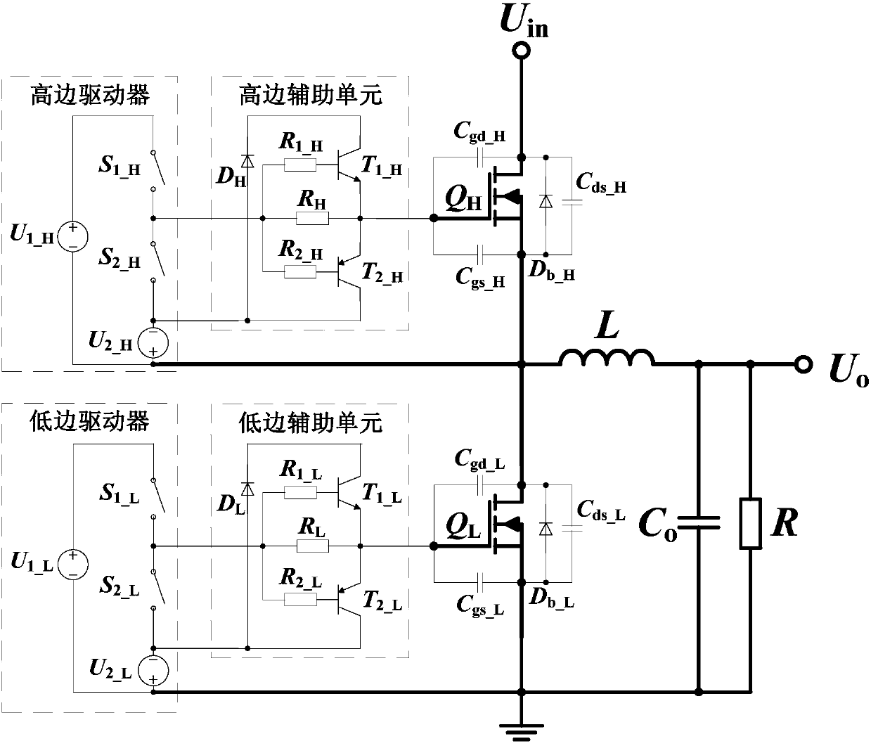
[0034] The working principle of the synchronous rectification Buck converter is as follows: figure 1 As shown, unlike the traditional Buck converter, it uses a switching tube Q L Replacing the rectifier diode is beneficial to improve the conversion efficiency of the entire converter. through the output voltage U o Sampling and processing, the control circuit generates an adjustable pulse width modulation signal PWM H and PWM L , and through the drive circuit, output the corresponding drive signal S H and S L , drive the high and low side switches respectively Q H and Q L , so that the converter at the input voltage U in regulation, the output voltage is maintained U o constant.
[0035] Compared with Si material switching tu...
PUM
 Abstract
Description
Claims
Application Information
 - R&D
- Intellectual Property
- Life Sciences
- Materials
- Tech Scout
- Unparalleled Data Quality
- Higher Quality Content
- 60% Fewer Hallucinations
Browse by: Latest US Patents, China's latest patents, Technical Efficacy Thesaurus, Application Domain, Technology Topic, Popular Technical Reports.
© 2025 PatSnap. All rights reserved.Legal|Privacy policy|Modern Slavery Act Transparency Statement|Sitemap|About US| Contact US: help@patsnap.com


