
A linear drive

A technology of linear transmission and transmission components, applied in the field of medical imaging, can solve the problems of unfavorable scanning image axial uniformity, increased motor loss, and high cost of linear motor, so as to avoid physical health damage, improve axial uniformity, avoid The effect of the end effect

Active Publication Date: 2020-06-16
JIANGSU SINOGRAM MEDICAL TECH CO LTD
View PDF4 Cites 0 Cited by
  • Summary
  • Abstract
  • Description
  • Claims
  • Application Information

AI Technical Summary

Problems solved by technology

[0004] First, due to the unavoidable end effect of the linear motor, that is, the magnetic field at the end of the linear motor is distorted, the loss of the motor increases, the thrust decreases, and there are large thrust fluctuations, so that the scanning table cannot be in the scanning area. Stable movement is not conducive to improving the axial uniformity of the scanned image; secondly, due to the need for magnetic isolation when installing the linear motor, it makes installation difficult; thirdly, the cost of the linear motor is relatively high, especially for long-stroke For linear motors, for example, the PET system requires the stroke of the patient's scanning bed to reach more than 1800mm, and the cost of such long-stroke linear motors is very high

Method used

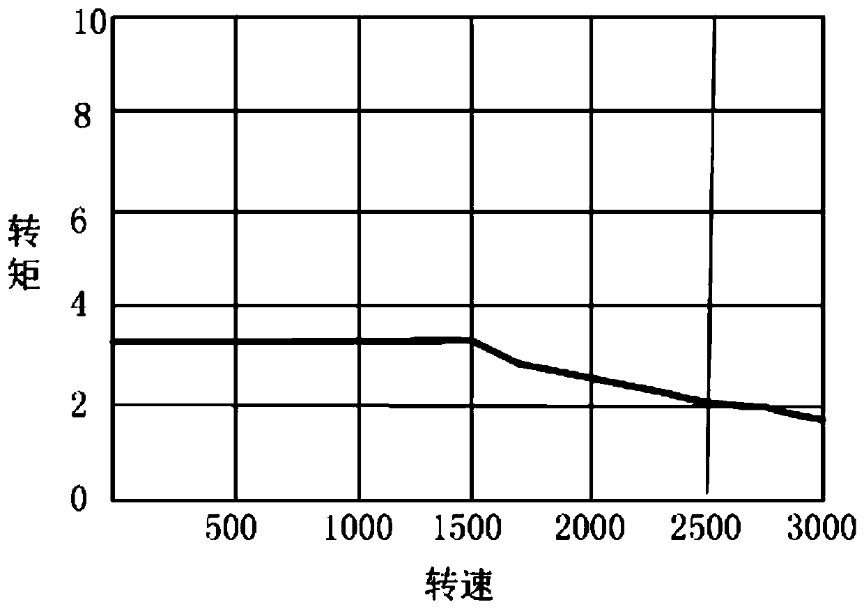
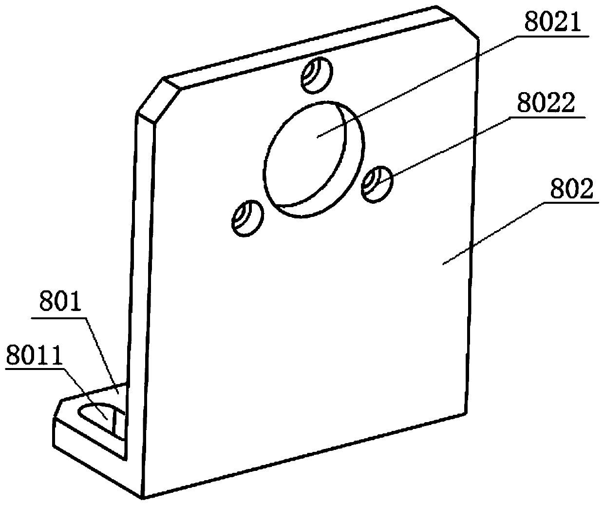

Image

  • A linear drive
  • A linear drive
  • A linear drive

Examples


Embodiment Construction

[0052] In order to make the object, technical solution and advantages of the present invention clearer, the implementation manner of the present invention will be further described in detail below in conjunction with the accompanying drawings.

[0053] The embodiment of the present invention provides a linear transmission device, such as figure 1 As shown, the device includes: a motor 1, a reducer 2, a clutch 3, and a transmission assembly 4 coaxially coupled in sequence; the transmission assembly 4 includes: a ball screw 401 coupled with the clutch 3, and a ball screw 401 adapted to the ball nut 402; the ratio of the lead of the ball screw 401 to the diameter of the ball screw 401 is 1.0 to 2.0; the rotation of the ball screw 401 can drive the ball nut 402 to make a linear motion; and, when the clutch 3 is powered off, it can Pull back the ball nut 402 manually, and drive the scanning bed with the patient on the ball nut 402 .

[0054] The working principle of the linear tra...


PUM


Abstract

The invention discloses a linear transmission device, and belongs to the field of medical imaging. The device comprises a motor, a speed reduction device, a clutch and a transmission assembly which are coaxially connected, wherein the transmission assembly comprises a ball screw connected with the clutch and a ball nut, the ball nut is adaptive to the ball screw, the ratio between the lead of theball screw and the diameter of the ball screw is 1.0-2.0, the ball nut can be driven to do linear motion by the ball screw, and when the clutch is powered off, the ball nut can be manually pulled anda scanning bed arranged on the ball nut and loaded with a patient can be driven. With the linear transmission device provided by the invention, low-speed linear motion can be achieved, an end effect of a linear motor having the same function can be effectively prevented on the premise that the scanning bed loaded with the patient can be pulled out of a scanning region, the scanning bed can be enabled to be in a uniform low-speed motion state within the whole scanning range, and the axial uniformity of a scanning image is improved.

Description

technical field [0001] The invention relates to the field of medical imaging, in particular to a linear transmission device. Background technique [0002] In the field of medical imaging, such as PET (Positron Emission Tomography, positron emission tomography) field, CT (Computed Tomography, electronic computer tomography) field, the patient usually lies on the scanning bed, and the linear rotation device is used to install it on it. The scanning table is sent horizontally into the scanning area, and then the patient is scanned and imaged. Different medical imaging fields require different axial movement speeds of the scanning table. For example, in the PET field, the scanning table does not move continuously during system imaging, but stops moving during system acquisition. After acquiring a part, The scanning table moves a preset distance and acquisition continues. However, in recent years, through theoretical research and practice, for the field of PET, the continuous m...

Claims


Application Information

Patent Timeline
Patent Type & Authority Patents(China)
IPC IPC(8): H02K7/06H02K11/21F16H25/20F16H25/22
CPCF16H25/2018F16H25/2204F16H2025/2075F16H2025/2087H02K7/06H02K11/21
Inventor 不公告发明人
Owner JIANGSU SINOGRAM MEDICAL TECH CO LTD
Learn More