Fuel cell stack structure

A fuel cell stack and electric stack technology, which is applied to fuel cells, fuel cell components, circuits, etc., can solve the problems of uneven internal resistance of the stack, inconsistent reaction efficiency, and large heat dissipation at the terminals, so as to ensure normal operation. Working conditions, ease of automated production, and reasonable packaging structure

Pending Publication Date: 2018-03-06
中氢新能源科技(深圳)有限公司
View PDF7 Cites 5 Cited by
  • Summary
  • Abstract
  • Description
  • Claims
  • Application Information

AI Technical Summary

Problems solved by technology

[0003] The fuel cell stack has a plurality of bipolar plates stacked, and collector plates, insulating plates, end plates and terminals are arranged at both ends of the stacked bipolar plates. Since the heat dissipation of the terminals is large at the connection with the collector plates, especially the packaging It is difficult to dissipate heat in the end plate, which reduces the service life of the battery stack, and the positive and negative stages are located at both ends of the fuel cell stack, which makes later assembly difficult and cumbersome
[0004] Moreover, the packaging structure of the current fuel cell stack cannot guarantee uniform and constant assembly pressure, so that the normal operation of the battery stack cannot be guaranteed and its service life is affected. One of the reasons is that there is contact resistance between the battery stack and the collector plate. If the pressure is not uniform, It will lead to uneven contact resistance, which in turn will cause uneven internal resistance of each point inside the battery stack and inconsistent reaction efficiency, resulting in inconsistent heat generation everywhere, easy to cause local overheating, and damage the battery stack. If the pressure is not constant, the battery's volt The safety characteristics are unstable, which leads to a decline in the parameter matching with the fuel cell stack control software, and the optimal control cannot be achieved
The second reason is that both the battery stack and the current collector plate have their maximum stress. Excessive local pressure may cause damage to the battery stack and gas leakage.

Method used


Image

  • Fuel cell stack structure
  • Fuel cell stack structure
  • Fuel cell stack structure

Examples


Embodiment 1

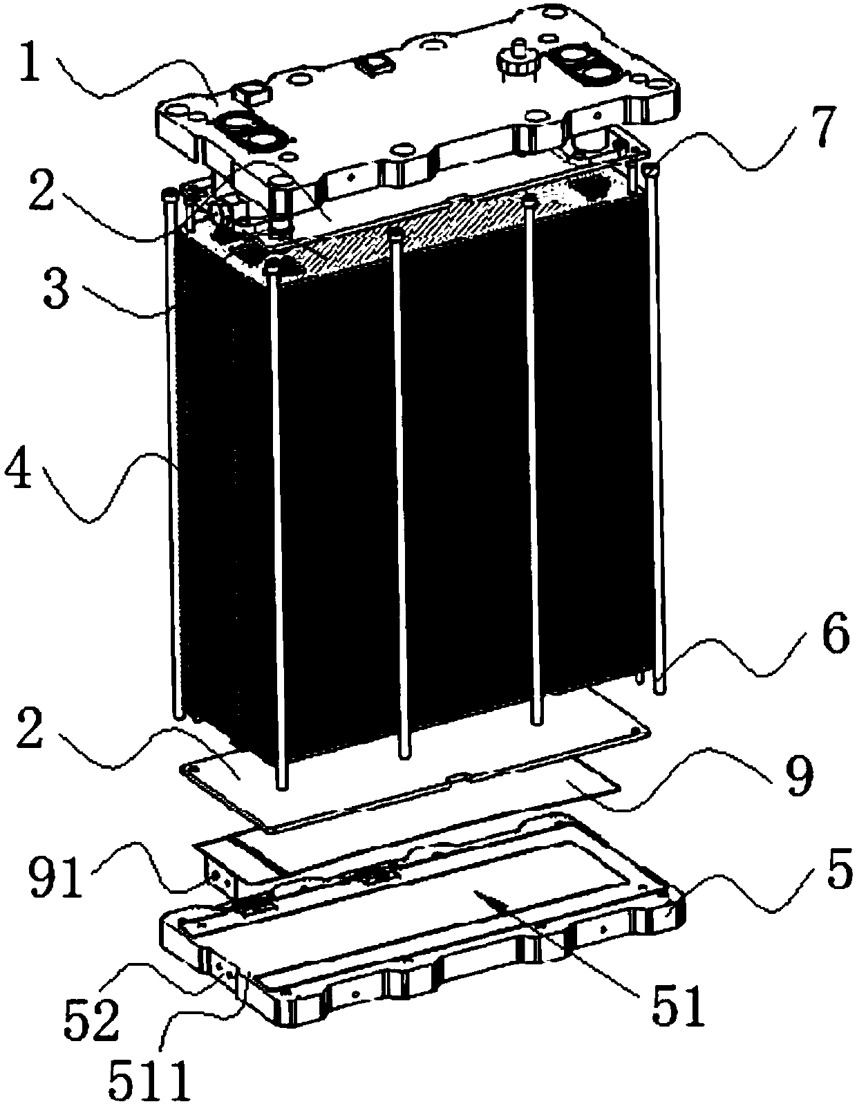
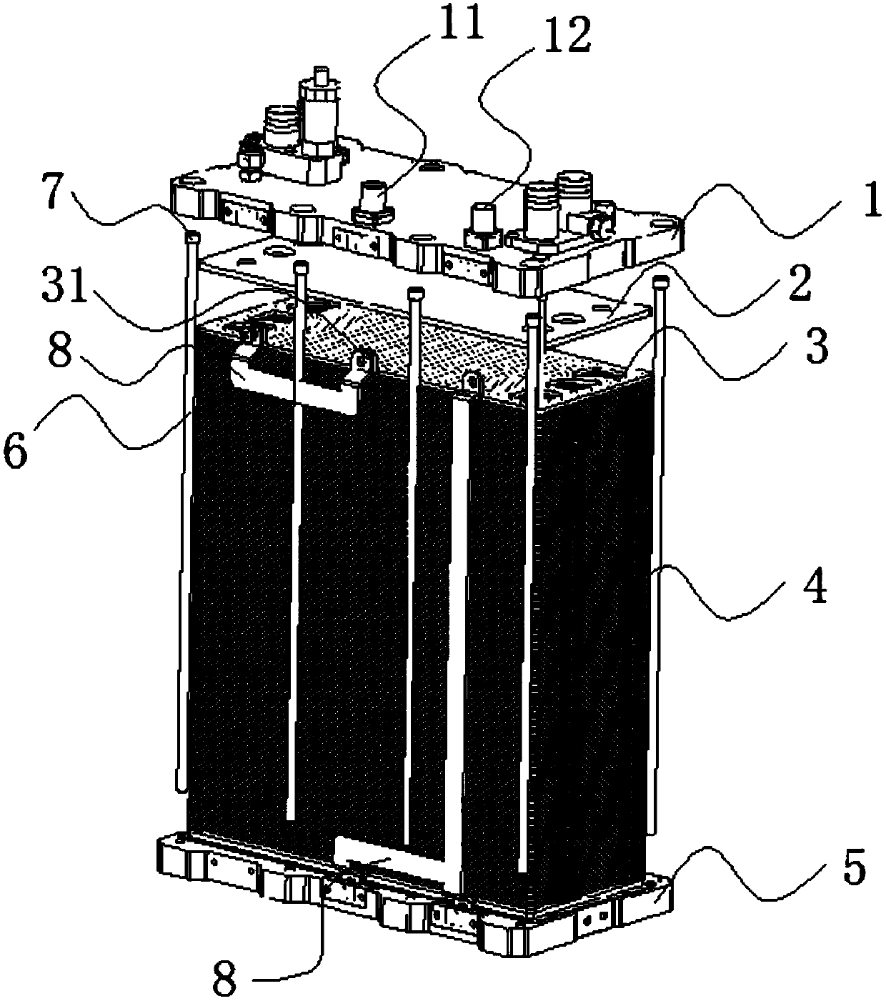
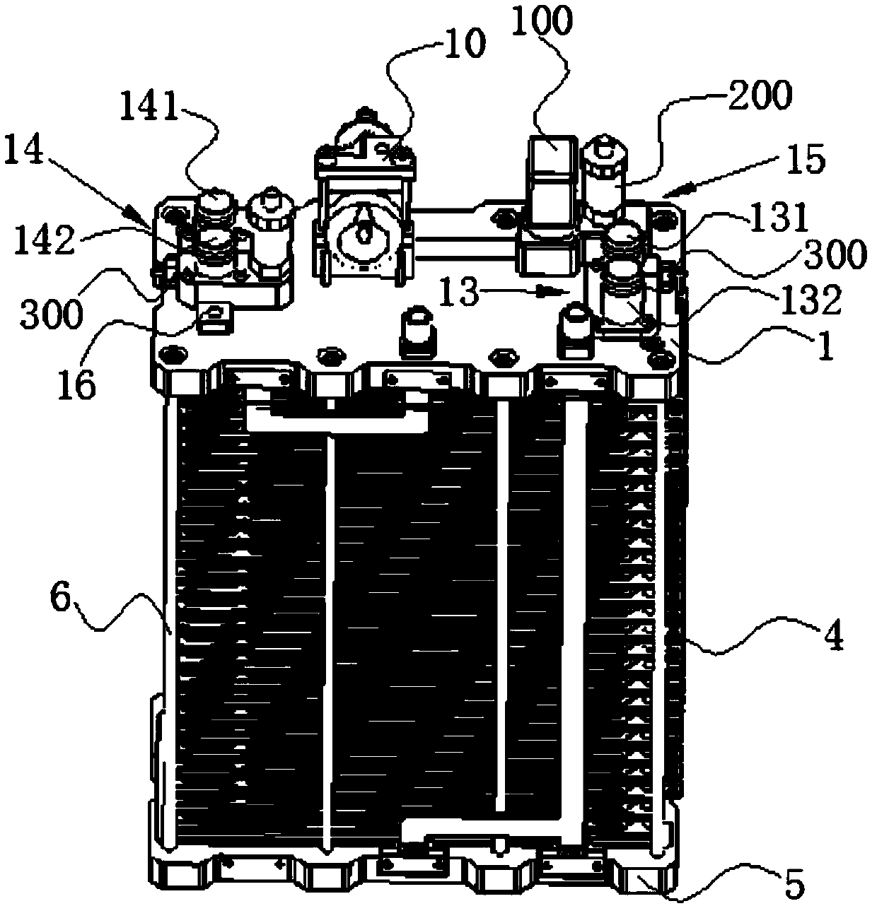
[0035] Embodiment 1: a fuel cell stack structure, such as Figure 1-Figure 4 As shown, it includes an upper end plate 1, an insulating plate 2, a collector plate 3, a stack body 4 and a lower end plate 5, the upper end plate 1 and the lower end plate 5 are parallel to each other, and the upper end plate 1 and the lower end plate 5, two insulating plates 2 are arranged between them, two collector plates 3 are arranged between the two insulating plates 2, and the stack body is arranged between the two collector plates 3 4;

[0036] It also includes several insulating fixing rods 6 located on the periphery of the stack body, the two ends of the insulating fixing rods 6 are respectively connected to the nuts 7 of the upper end plate 1 and the nuts 7 of the lower end plate 5, and the nuts of the nuts 7 The inner surface has internal threads matching the external threads at both ends of the insulating fixing rod 6;

[0037] The upper surface of the lower end plate 5 has a concave ...

Embodiment 2

[0050] Embodiment 2: a fuel cell stack structure, such as Figure 1-Figure 5 As shown, the structure of the second embodiment is similar to that of the first embodiment, the difference is that the elastic support is a spring 400, and the center of the bottom surface of the groove is provided with a positioning hole 512 matching the spring , one end of the spring is fixed in the positioning hole, and the other end of the spring is in contact with the lower surface of the insulating plate.

[0051] The working principle of the present invention is as follows: the two ends of the insulating fixing rod of the present invention are respectively connected with the nuts of the upper end plate and the nuts of the lower end plate, the packaging structure is reasonable, the cost is low, and it is convenient for automatic production. The upper surface of the lower end plate has a concave groove The groove and the elastic support between the groove and the insulating plate provide uniform...


PUM

PropertyMeasurementUnit
thicknessaaaaaaaaaa
widthaaaaaaaaaa
thicknessaaaaaaaaaa

Abstract

The invention discloses a fuel cell stack structure which comprises an upper end plate, two insulating plates, two collector plates, a stack body and a lower end plate; the upper end plate is mutuallyparallel to the lower end plate; the two insulating plates are arranged between the upper end plate and the lower end plate; the two collector plates are arranged between the two insulating plates; and the stack body is arranged between the two collector plates. The fuel cell stack structure also comprises a plurality of insulation fixed rods which are arranged at the periphery of the stack body;the two ends of the insulation fixed rods are connected with nuts of the upper end plate and nuts of the lower end plate respectively; and the inner surface of each nut is provided with inside threads which are matched with outside threads of each of the two ends of the insulation fixed rods. By adopting the fuel cell stack structure, uniform and constant assembly pressure is provided for the interior of the cell stack, so that the lower surface of the stack body is uniformly stressed, the normal working condition of the cell stack is ensured, the service life of the cell stack is prolonged;and power supply terminals of an anode and a cathode are arranged on one end plate, so that wiring assembly in later period is convenient, gas leakage is prevented, and the energy is saved.

Description

technical field [0001] The invention belongs to the technical field of battery structures, in particular to a fuel cell stack structure. Background technique [0002] In today's global energy shortage and high oil prices, it is imperative to find new energy as a substitute for fossil fuels. Fuel cells are considered to be the fourth-generation power generation technology after hydropower, thermal power and atomic power generation. It directly converts the chemical energy of oxidants and reductants into electrical energy through electrocatalytic reactions. It is an efficient, safe, clean and flexible new type of power generation technology. power generation technology. Among them, the proton exchange membrane fuel cell has a wide range of application prospects in ground power stations, electric vehicles and portable power sources due to its remarkable advantages such as high efficiency, high energy density, low reaction temperature, no noise, and no pollution. [0003] The ...

Claims


Application Information

Patent Timeline
Patent Type & Authority Applications(China)
IPC IPC(8): H01M8/0202H01M8/04746H01M8/2465H01M8/2483H01M8/248H01M8/247
CPCH01M8/0202H01M8/04753H01M8/2465H01M8/247H01M8/248H01M8/2483Y02E60/50
Inventor 邱耀弘夏泮文张骞为徐国兵
Owner 中氢新能源科技(深圳)有限公司
Why Eureka
Try Eureka