
Method and device for operation state detection of permanent magnet synchronous motor

A permanent magnet synchronous motor and operating state technology, which is applied to measuring devices, motor generator testing, measuring electricity, etc., can solve problems such as difficulty in application, identification of abnormal state of the motor, and the inability to directly obtain the rotor position in a position sensorless control scheme, etc. To achieve the effect of simple and accurate judgment

Active Publication Date: 2018-03-06
GREE ELECTRIC APPLIANCES INC +1
View PDF8 Cites 7 Cited by
  • Summary
  • Abstract
  • Description
  • Claims
  • Application Information

AI Technical Summary

Problems solved by technology

[0003] However, since the position sensorless control scheme cannot directly obtain the current rotor position, when the motor loads the fan blade or the rotor is stuck and an abnormality occurs, the controller cannot identify the current abnormal state of the motor through the rotor position
[0004] At present, the DC motor of the position sensorless control scheme mainly judges the stall state of the motor by collecting the magnitude of the three-phase current, but for the torque current control method, it is impossible to judge the abnormal stall problem through its three-phase current
At the same time, if the three-phase overcurrent is used to judge the abnormal state of the motor stall, the current limiting protection of the motor cannot be performed. Therefore, it is difficult to use in some occasions that require current limiting.
[0005] For the above problems, no effective solutions have been proposed so far

Method used


Image

  • Method and device for operation state detection of permanent magnet synchronous motor
  • Method and device for operation state detection of permanent magnet synchronous motor
  • Method and device for operation state detection of permanent magnet synchronous motor

Examples


Embodiment Construction

[0060] In order to make the object, technical solution and advantages of the present invention clearer, the present invention will be further described in detail below in conjunction with the embodiments and accompanying drawings. Here, the exemplary embodiments of the present invention and their descriptions are used to explain the present invention, but not to limit the present invention.

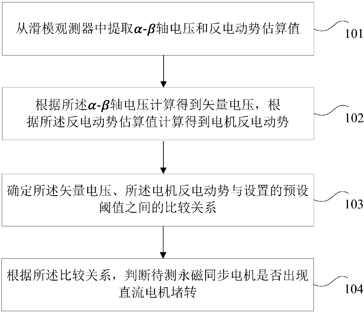
[0061] In the embodiment of the present invention, a detection method is proposed to determine whether the DC motor is stalled by inputting the relationship between the effective vector voltage of the motor and the back electromotive force of the motor, such as figure 1 As shown, the running state detection method of the permanent magnet synchronous motor may include:

[0062] Step 101: extracting α-β axis voltage and back EMF estimated values ​​from the sliding mode observer;

[0063] Specifically, the α-β axis voltage and the estimated value of the back EMF can be extracted from the foll...


PUM


Abstract

The present invention provides a method and a device for operation state detection of a permanent magnet synchronous motor. The method comprises the steps of: extracting an [Alpha]-[Beta] axis voltageand a counter electromotive force estimated value from a sliding-mode observer; calculating and obtaining a vector voltage according to the [Alpha]-[Beta] axis voltage, and calculating and obtaininga motor counter electromotive force according to the counter electromotive force estimated value; determining a comparison relation among the vector voltage, the motor counter electromotive force anda preset threshold value; and determining whether a permanent magnet synchronous motor to be detected generates stalling of the direct current motor or not according to the comparison relation. According to the embodiment of the invention, the problems are solved that stalling identification cannot be performed by a torque current control mode and a current-limiting function design cannot be performed when an overcurrent mode is used for stalling identification, and therefore a technical effect of simply and accurately determining whether a direct current motor stalling problem happens or notcan be achieved.

Description

technical field [0001] The invention relates to the technical field of motor control, in particular to a method and device for detecting the running state of a permanent magnet synchronous motor. Background technique [0002] At present, the permanent magnet synchronous motor has the characteristics of high power density, high efficiency, low loss, small size and simple structure, and the permanent magnet synchronous motor with no position sensor control scheme has the advantages of simple assembly, wide application, high reliability and The advantages of low cost have been used more and more widely. [0003] However, since the position sensorless control scheme cannot directly obtain the current rotor position, when the motor loads the fan blade or the rotor is stuck and an abnormality occurs, the controller cannot identify the current abnormal state of the motor through the rotor position. [0004] At present, the DC motor of the position sensorless control scheme mainly ...

Claims


Application Information

Patent Timeline
IPC IPC(8): G01R31/34
CPCG01R31/343
Inventor 吴文贤郭伟林孙家广胡安永
Owner GREE ELECTRIC APPLIANCES INC
Learn More