Automatic electric pole erecting device

The utility model relates to an electric pole and automatic technology, which is applied in the field of automatic electric pole devices, and can solve the problems of endangering the safety of construction workers, collapse of the tripod of the electric pole, affecting the efficiency of electric power construction, etc., and achieve the effect of improving work accuracy and work efficiency.

Inactive Publication Date: 2018-03-06
国网江西省电力有限公司九江供电分公司 +2
View PDF5 Cites 3 Cited by
  • Summary
  • Abstract
  • Description
  • Claims
  • Application Information

AI Technical Summary

Problems solved by technology

[0004] Aiming at the deficiencies in the prior art, the purpose of the present invention is to provide an automatic erecting pole device to solve the problem that the automatic erecting pole device in the prior art cannot be changed in multiple gears and cannot be freely controlled according to the actual situation of erecting the pole. Hanging speed, fixed speed, may cause the pole to slip or the tripod to collapse due to the high speed, endangering the safety of the construction personnel, or the defect that affects the efficiency of electric power construction due to the slow speed

Method used


Image

  • Automatic electric pole erecting device
  • Automatic electric pole erecting device
  • Automatic electric pole erecting device

Examples


Embodiment Construction

[0021] In order to make the technical means, creative features, goals and effects achieved by the present invention easy to understand, the present invention will be further described below in conjunction with specific embodiments.

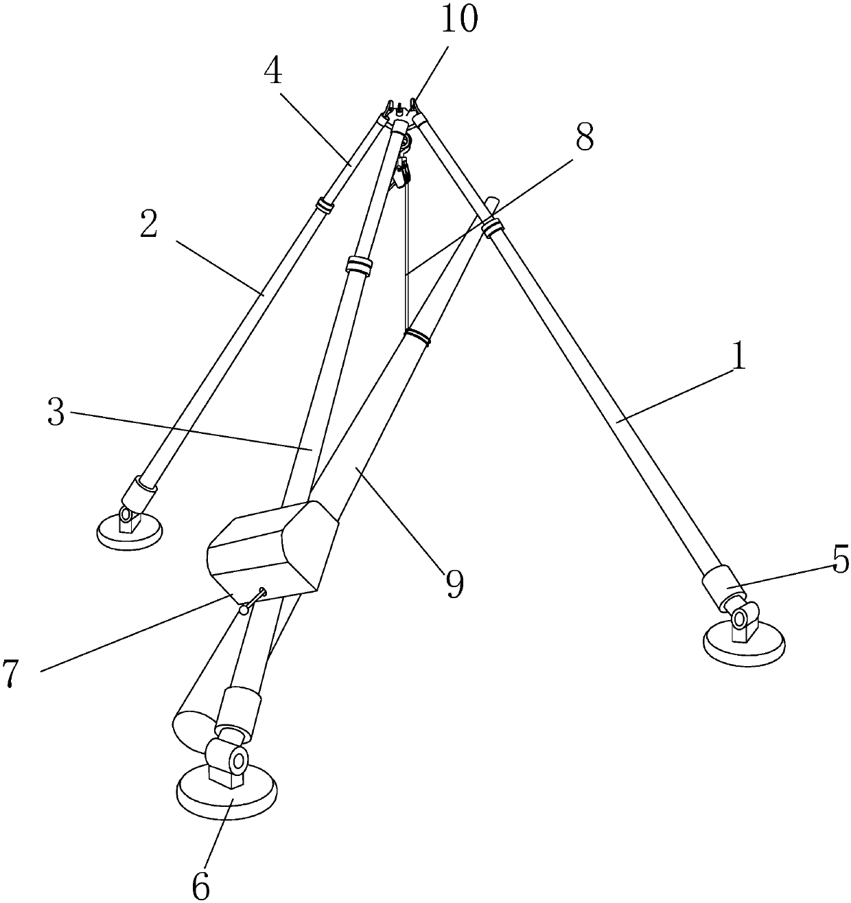
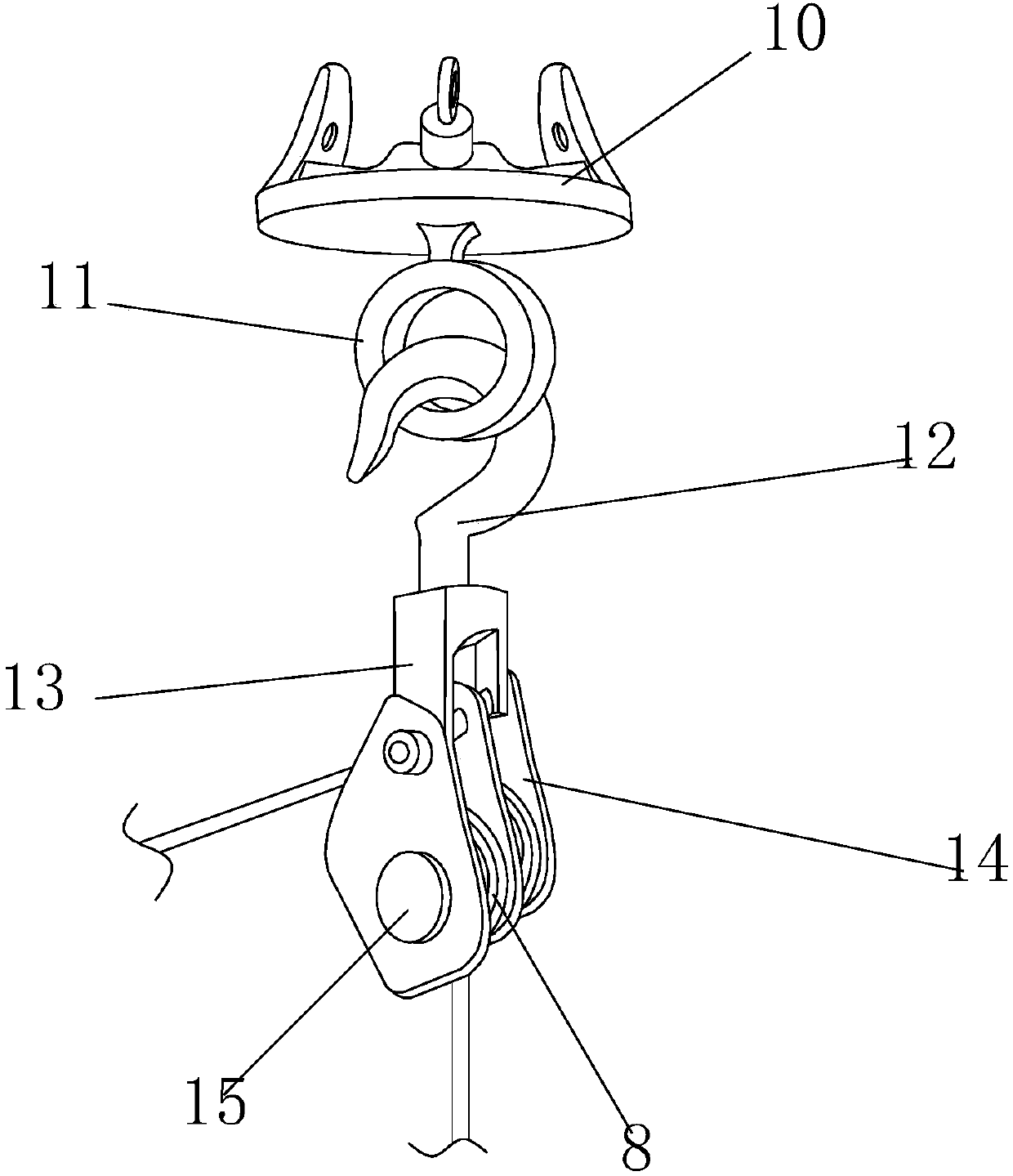
[0022] see Figure 1-Figure 6, the present invention provides a technical solution for an automatic erecting pole device: its structure includes a first auxiliary pole 1, a second auxiliary pole 2, a main pole 3, a telescopic pole 4, a connecting sleeve 5, a fixed foot plate 6, a multi-block twist Line device 7, lifting oil wire 8, electric pole 9, top bearing plate 10, connection hanging ring 11, hook 12, connector 13, fixed pulley frame 14, fixed pulley 15, and the first auxiliary rod 1 is arranged on the main At the right rear of the rod 3, the second sub-rod 2 is arranged at the left rear of the main rod 3 and is symmetrical to the first sub-rod 1, and the telescopic rod 4 is arranged at the first sub-rod 1, the second sub-rod 2, and the main ...


PUM

PropertyMeasurementUnit
Diameteraaaaaaaaaa
Diameteraaaaaaaaaa
Diameteraaaaaaaaaa

Abstract

The invention discloses an automatic electric pole erecting device. The automatic electric pole erecting device structurally comprises a first auxiliary rod, a second auxiliary rod, a main rod, a telescopic rod, a connecting sleeve, a fixing bottom plate, a multi-gear wire stranding device, a hoisting oil wire, an electric pole, a top force bearing plate, a connecting hanging ring, a hanger, a connecting piece, a fixed pulley frame and a fixed pulley. The first auxiliary rod is arranged on the rear right portion of the main rod, and the second auxiliary rod is arranged on the rear left portionof the main rod and is symmetrical with the first auxiliary rod. The automatic electric pole erecting device has the beneficial effects that the multi-gear wire stranding device is arranged, according to the actual condition of electric pole hoisting erection, the hoisting erection speed of the electric pole can be freely controlled by changing the gears, and thus the effects that in preliminaryhoisting erection, the electric pole is erected in a hoisted mode at the first gear of the low speed to test whether the automatic electric pole erecting device can bear the weight of the electric pole or not so as to protect the device and ensure the safety of constructers, in the hoisting erection medium-term, the electric pole is erected in the hoisted at the speeds of the second gear and the third gear to improve the work efficiency, and when hoisting erection is about to be finished, the electric pole is erected in the hoisted accurately at the speed of the first gear to be vertical so asto improve the work accuracy are achieved.

Description

technical field [0001] The invention is an automatic pole erecting device, which belongs to the technical field of electric power engineering equipment. Background technique [0002] Electric power engineering refers to engineering related to the production, transmission, and distribution of electric energy. In a broad sense, it also includes engineering that uses electricity as power and energy in various fields. At the same time, it can be understood that the power transmission and transformation industry expansion project. [0003] However, the automatic pole erection device of the prior art cannot be changed in multiple gears, and the erection speed cannot be freely controlled according to the actual situation of the pole erection. The fixed speed may cause the pole to slip or the tripod to fail due to the high speed. It collapses due to bearing, endangering the safety of construction personnel, or affecting the efficiency of power construction due to slow speed. Cont...

Claims


Application Information

Patent Timeline
IPC IPC(8): E04H12/34
Inventor 陈春渊张艳丽张雄
Owner 国网江西省电力有限公司九江供电分公司
Why Eureka
Try Eureka