
An installation process for deep-buried earth pressure cells

A technology of earth pressure box and installation process, which is applied in the direction of basic structure engineering, basic structure test, construction, etc., can solve the problems of cable breakage, pressure box overturning, easy to cut lines, etc., to reduce the number of cables being cut, Effects of preventing errors in measurement data and expanding applicability

Active Publication Date: 2019-11-12
中煤浙江测绘地理信息有限公司
View PDF5 Cites 0 Cited by
  • Summary
  • Abstract
  • Description
  • Claims
  • Application Information

AI Technical Summary

Problems solved by technology

Because the earth pressure box is mostly round, it is difficult to tie it up, which may easily cause the pressure box to overturn, resulting in untrue monitoring data in the future; in addition, the cables are all bare wires, which are easy to cut off the line or due to friction with the surrounding hard objects. Cause the cable to break, thus affecting the monitoring quality

Method used


Image

  • An installation process for deep-buried earth pressure cells
  • An installation process for deep-buried earth pressure cells
  • An installation process for deep-buried earth pressure cells

Examples


Embodiment 1

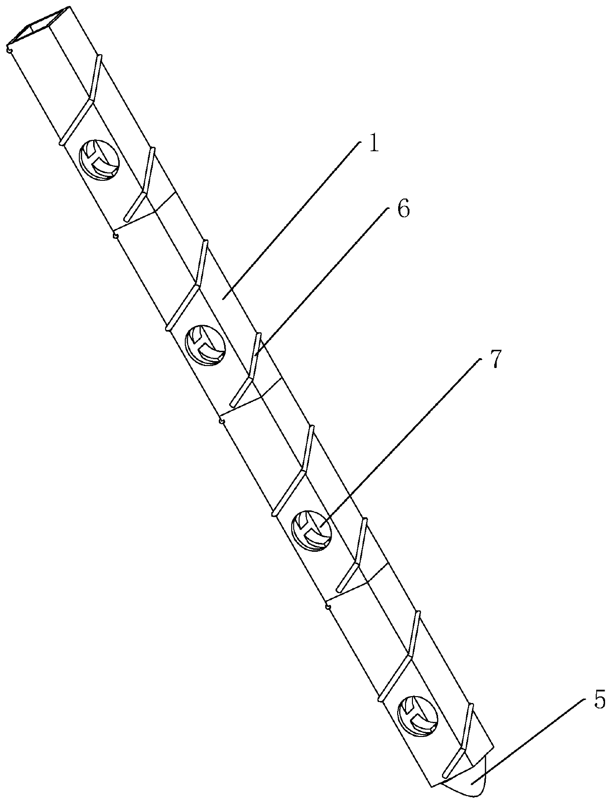
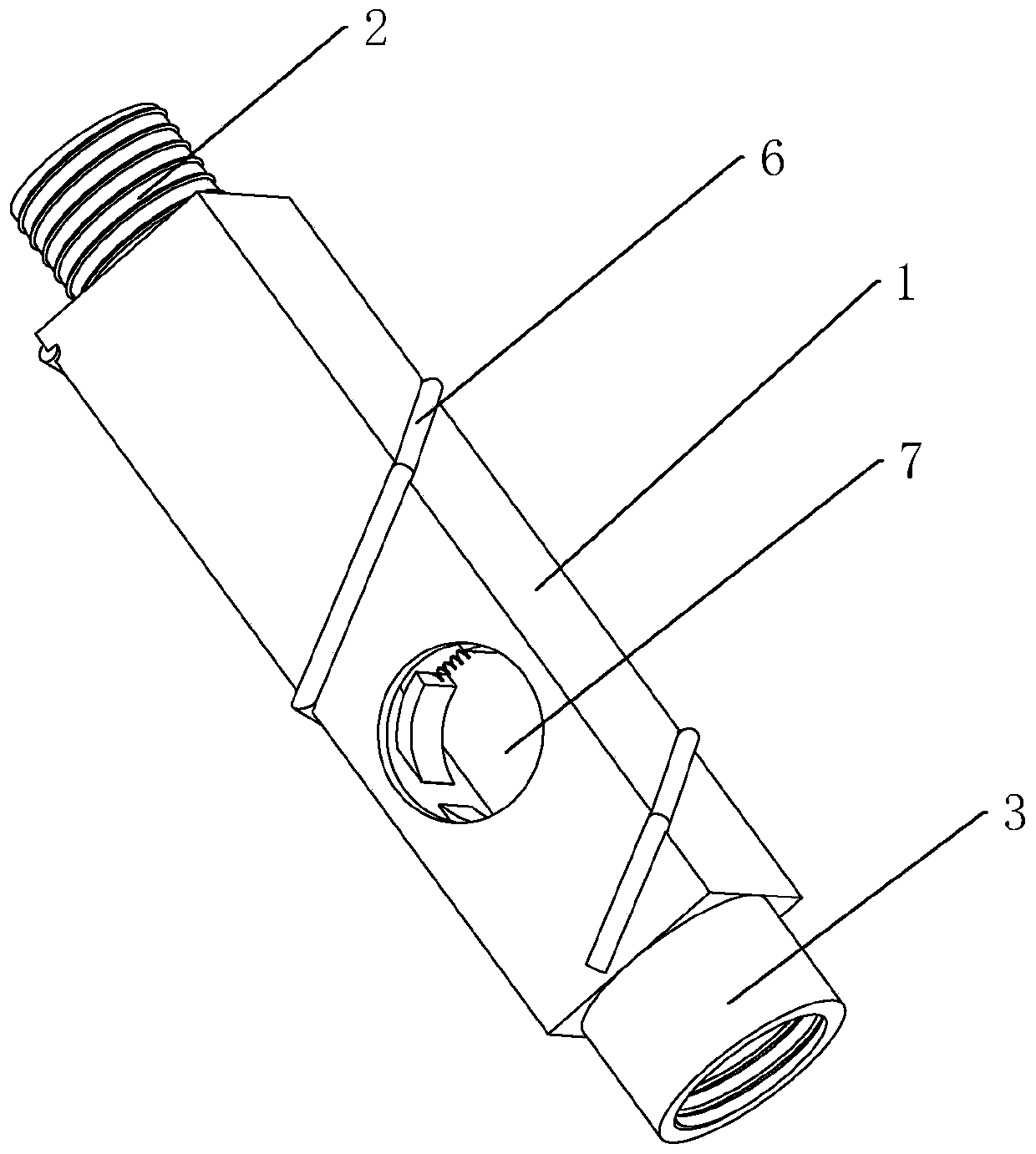
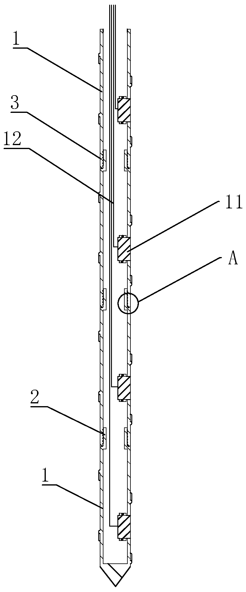
[0046] Such as figure 1 As shown, a casing assembly used for the installation of a deep-buried earth pressure box, the casing assembly includes a plurality of casings 1, the casing 1 is a square tube and the casing 1 is made of PVC. Such as figure 2 As shown, both ends of the sleeve 1 are fixedly provided with a first connecting piece 2 and a second connecting piece 3 respectively. Such as image 3 As shown, the lowermost sleeve 1 is provided with only the first connecting piece 2 and the uppermost sleeve 1 is provided with only the second connecting piece 3. Such as figure 2 As shown, the outer wall of the first connecting member 2 is provided with external threads, and the inner wall of the second connecting member 3 is provided with internal threads. The first connector 2 of the sleeve 1 can be screwed to the second connector 3 of another sleeve 1. Such as image 3 As shown, when two sleeves 1 need to be connected, only the first connecting piece 2 of one sleeve 1 needs t...

Embodiment 2

[0052] An installation process for a deep-buried earth pressure box, which is characterized in that the casing 1 in the first embodiment is used and includes the following steps:

[0053] S1. Insert the earth pressure box 11 into the mounting hole 7 so that the earth pressure box 11 is fixedly installed on the casing 1, and the axial direction of the earth pressure box 11 is perpendicular to the axial direction of the casing 1; at the same time, the first clamping plate 8 and The second clamping plate 9 simultaneously presses the earth pressure box 11 under the action of the pressing spring 10, so that the earth pressure box 11 is installed in the casing 1 more stably;

[0054] S2. Arrange all the casings 1, and then pass the cable 12 on the earth pressure box 11 through all the casings 1, so that the upper end of the cable 12 passes through the uppermost casing 1, and then all the casings 1 Installed together section by section; such as image 3 Shown

[0055] S3. Fill the casing 1...


PUM


Abstract

The invention discloses an installation process used for deeply-buried earth pressure cells. The installation process used for the deeply-buried earth pressure cells comprises the following steps thatS1, casing pipes provided with installation holes are selected; S2, the earth pressure cells are arranged in the installation holes in an embedded manner to be fixedly arranged on the casing pipes, and the axial directions of the earth pressure cells are perpendicular to the axial directions of the casing pipes; S3, all the casing pipes are arranged one by one in the axial directions of the casing pipes, a cable corresponding to the earth pressure cells penetrates the casing pipes, the upper end of the cable penetrates out of the upmost casing pipe, and the lower end of the lowest casing pipeis closed; S4, all the casing pipes are fixedly installed together in the axial directions of the casing pipes; S5, the casing pipes are full of standard sand, and the standard sand is compacted; S6,drilling mechanical equipment is adopted to drill a hole with enough depth; and S7, the casing pipes with the earth pressure cells are sequentially put into the holes, and gaps on the outer sides ofthe casing pipes are full of standard sand. The casing pipes play a role in limiting the earth pressure cells, so that the earth pressure cells can be stably buried in the soil layer, and errors, caused by overturning of the earth pressure cells, of measured data is prevented.

Description

Technical field [0001] The invention relates to the technical field of construction engineering, in particular to an installation process for a deep buried earth pressure box. Background technique [0002] The deep-buried earth pressure cell is used to measure the changes of the mechanical parameters of various soil layers below the surface. Measure the earth pressure changes at different depths of the undisturbed soil, and provide early warning to ensure construction safety. [0003] The current method of burying the ground connecting wall pressure box is to first use hanging cloth to cover the side of the steel cage, and then tie the earth pressure box and the cable with iron wire, and the cable is tied to the top of the steel cage to extend about 1.5 meters. Because the earth pressure box is mostly round, it is difficult to bundle it, which will easily cause the pressure box to turn over and cause the subsequent monitoring data to be untrue; in addition, the cable lines are all...

Claims


Application Information

Patent Timeline
Patent Type & Authority Patents(China)
IPC IPC(8): E02D33/00
CPCE02D33/00
Inventor 王德传王孟王怡
Owner 中煤浙江测绘地理信息有限公司
Learn More