robot controller

A control device and robot technology, applied in program control, general control system, program control manipulator, etc., can solve problems such as decreased tracking accuracy and deviation.

Active Publication Date: 2020-02-28
FANUC LTD
View PDF8 Cites 0 Cited by
  • Summary
  • Abstract
  • Description
  • Claims
  • Application Information

AI Technical Summary

Problems solved by technology

[0009] In addition, when the workpiece cannot be detected by the camera, the position of the workpiece is calculated based on the equation of motion of the workpiece regardless of whether a part of the workpiece enters the field of view of the camera, so there is a gap between the calculated workpiece position and the actual workpiece position. There is a deviation, which leads to the problem of decreased tracking accuracy

Method used


Image

  • robot controller
  • robot controller
  • robot controller

Examples


Embodiment Construction

[0027] Hereinafter, embodiments of the robot system related to the present invention will be described in detail with reference to the drawings. It should be noted that in this manual, the ^ symbol marked above the English letter means "(English letter) hat ", the horizontal bar symbol added above the English letter means "(English letter) bar ", the dot mark marked above the English letter means "(English letter) dot ".

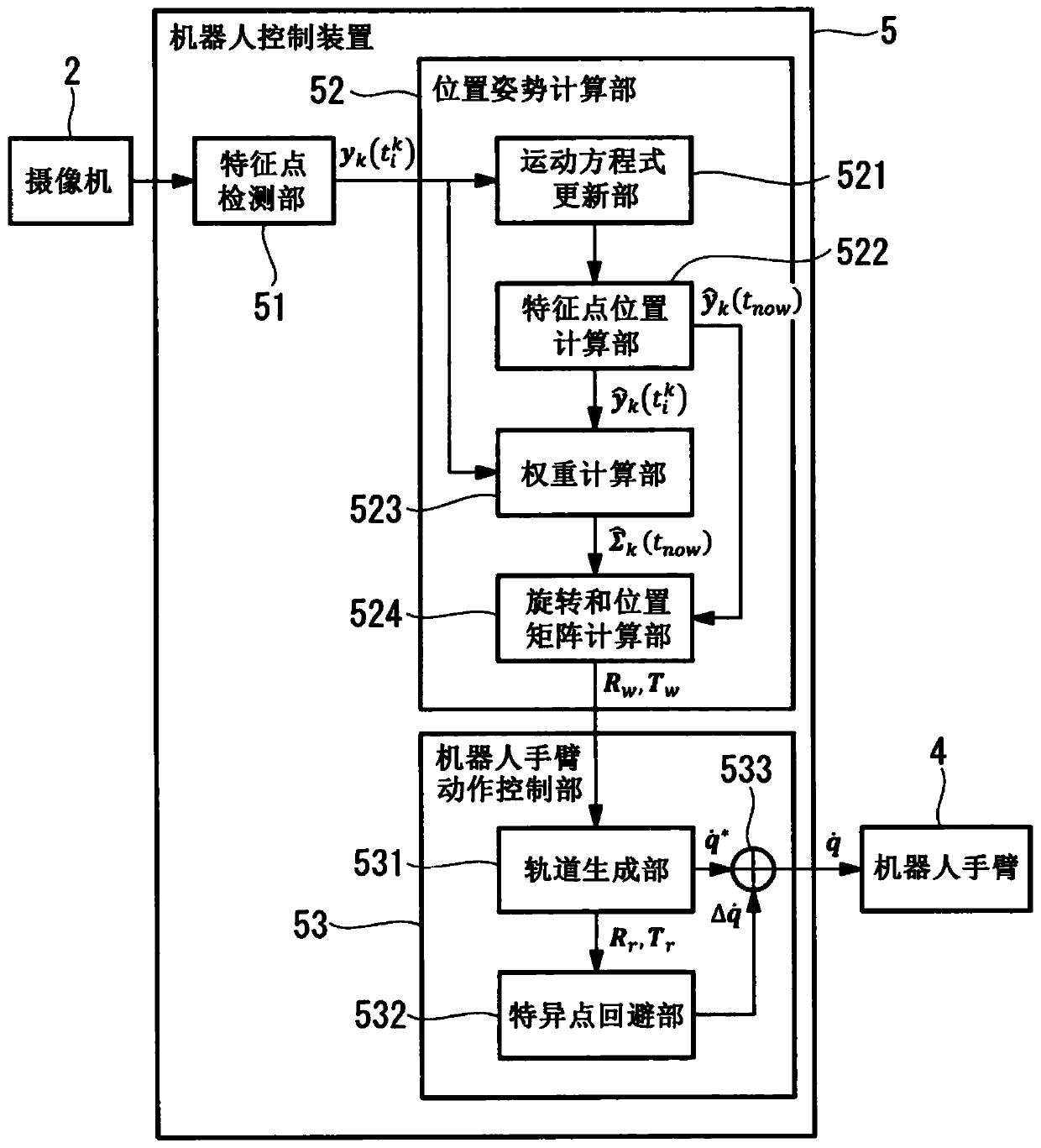
[0028] Such as figure 1 It is shown that the robot system 1 of this embodiment has a camera 2, a stand 3 for supporting the camera 2, a robot arm 4, and a robot control device 5 to which the camera 2 and the robot arm 4 are connected. The robot control device 5 is configured to perform visual servo control based on the visual information acquired from the camera 2 so that the robot arm 4 follows the movement of the workpiece (object) 7.

[0029] The workpiece 7 is placed on a conveying device 6 such as a conveyor belt or a rotating table, and the workpiece 7 m...


PUM


Abstract

Provided is a robot control device (5), capable of enabling a robot arm to follow an arbitrarily moving workpiece with high precision. The robot control device (5) includes: a feature point detection unit (51) configured to detect the positions of a plurality of feature points in the object from an image of the object captured by a visual sensor at a predetermined cycle; a position and posture calculation unit (52), based on the positions of the detected multiple feature points, update the respective motion equations of the multiple feature points in each predetermined period, and based on the respective positions of the multiple feature points calculated according to the updated motion equations , calculate the position or posture of the object; and the robot arm motion control unit (53), based on the calculated position or posture of the object, controls the motion of the robot arm (4) to follow the object.

Description

Technical field [0001] The invention relates to a robot control device suitable for controlling a robot arm through visual servoing. Background technique [0002] Conventionally, as a technology for controlling a robot arm, it is known that the position and posture of a continuously moving workpiece (object) are continuously measured by visual sensors such as a camera, and the robot arm follows the object based on the measurement result. Visual servoing (for example, refer to Patent Document 1 and Patent Document 2). [0003] Prior art literature [0004] Patent literature [0005] Patent Document 1: Japanese Patent No. 4265088 [0006] Patent Document 2: Japanese Patent Application Publication No. 2011-143494 Summary of the invention [0007] The problem to be solved by the invention [0008] However, in the robot control devices described in Patent Document 1 and Patent Document 2, since the moving speed of the fixed workpiece is assumed as a condition, there is a problem that the ro...

Claims


Application Information

Patent Timeline
Patent Type & Authority Patents(China)
IPC IPC(8): B25J13/08B25J9/16
CPCB25J9/1602B25J13/08G05B2219/39391G05B2219/40022G05B2219/40565B25J9/1697
Inventor 王凯濛陈文杰
Owner FANUC LTD
Why Eureka
Try Eureka