
I steel hogging machine

An I-beam and arch-bending technology is applied in the field of I-beam arch bending machines, which can solve problems such as troublesome time-consuming and lack of real-time performance.

Inactive Publication Date: 2018-03-06
晏满齐
View PDF0 Cites 0 Cited by
  • Summary
  • Abstract
  • Description
  • Claims
  • Application Information

AI Technical Summary

Problems solved by technology

The I-beam arch bending machine is manually balanced, which is troublesome and time-consuming, and has no real-time performance

Method used


Image

  • I steel hogging machine
  • I steel hogging machine

Examples


Embodiment Construction

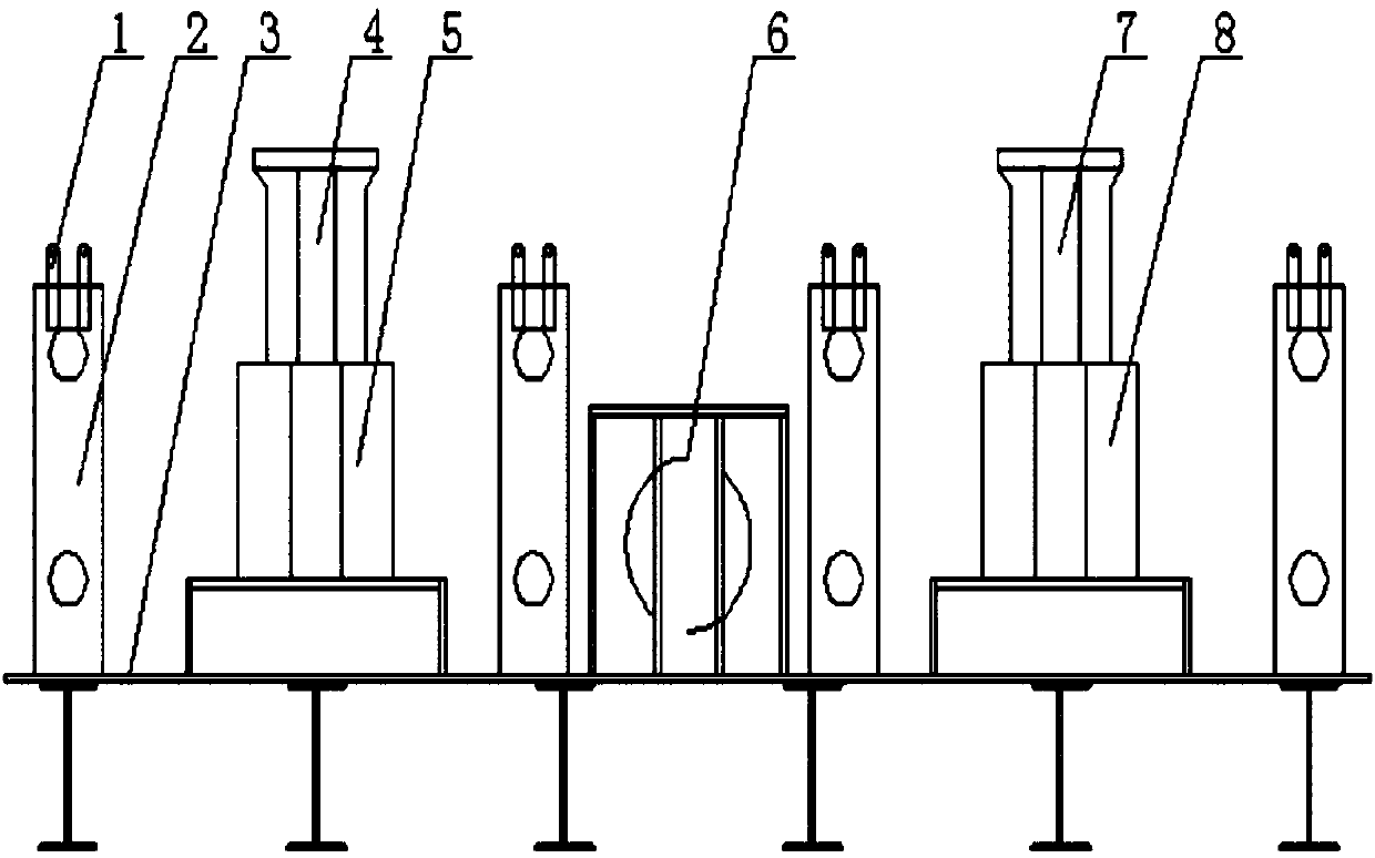
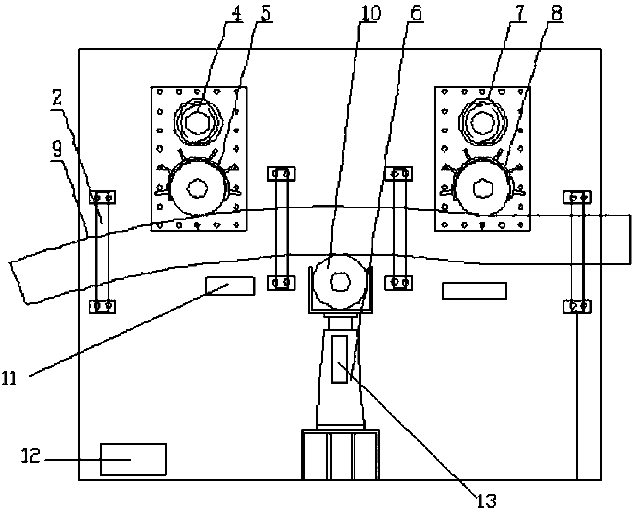
[0027] exist figure 1 , In the embodiment shown in 2, the present invention includes a workbench 1, a push wheel 2, an electric adjustment rail 3, a handle 4, a pusher 5, a first driving wheel 6, a second driving wheel 7, and a first driving device 8 , the second driving wheel 9, the second driving device 10, the photoelectric sensor 11, the controller 12, the pressure sensor 13.

[0028] Including workbench (1), push wheel (2), electric adjustment rail (3), handle (4), workbench (5), pusher (6), first driving wheel (7), second driving wheel wheel (8), first driving device (9), second driving wheel (10), second driving device, photoelectric sensor (11), controller (12), pressure sensor (13), it is characterized in that the A driving wheel and a pushing wheel are arranged on the workbench, and an adjusting rail arranged in parallel is also arranged; the driving wheel is connected with a driving device, and the pushing wheel is connected with a pusher. It is characterized in t...


PUM


Abstract

In order to overcome the deficiencies of the existing I-beam arch bending machine, the present invention provides an I-beam arch bending machine, which includes a workbench, a push wheel, an electric adjustment rail, a handle, a pusher, a first active Wheel, second driving wheel, first driving device, second driving wheel, second driving device, photoelectric sensor, controller, pressure sensor; the I-beam arch bending machine has a pressure sensor, an automatic balance bar, and an automatic balance function .

Description

technical field [0001] The invention relates to a device in the technical field of mechanical machine tools, in particular to an I-beam arch bending machine with a pressure sensor, an automatic balance bar and an automatic balance function. Background technique [0002] Arch bending machine is also called stretch bending machine, which can be divided into rotary table stretch bending machine, double arm type stretch bending machine and various special stretch bending machines, such as special stretch bending machine for shower room, special stretch bending machine for train top beam, elevator Dedicated bending machine. The stretch bending machine adopts full hydraulic control, which is easy to operate and high in production efficiency. It can cold bend various steel pipes, square pipes, H-beams, I-beams, channel steels, angle irons, flat irons and aluminum profiles with sections below 500mm. After bending, the arc shape is perfect, with high precision, good stability and no...

Claims


Application Information

Patent Timeline
Patent Type & Authority Applications(China)
IPC IPC(8): B21D7/06B21D7/16
CPCB21D7/06B21D7/16
Inventor 晏满齐
Owner 晏满齐
Learn More