Self-rehabilitation training bed for lower limb function of patient

A rehabilitation training and lower limb technology, applied in passive exercise equipment, physical therapy, etc., can solve problems such as motor function degradation, muscle atrophy, and inability to adjust the position of armrests, and achieve the effect of increasing the applicable population and increasing the scope of application

Inactive Publication Date: 2018-03-06
陕西专壹知识产权运营有限公司
View PDF8 Cites 0 Cited by
  • Summary
  • Abstract
  • Description
  • Claims
  • Application Information

AI Technical Summary

Problems solved by technology

[0002] At present, there are many cases of lower limb dysfunction and obstacles caused by sequelae of cerebrovascular disease, brain tumor, craniocerebral trauma, limb joint disease, etc. It will cause muscle atrophy, degeneration of motor function, and unable to take care of oneself
For such patients, self-physical function exercise on the auxiliary bed is very critical, so the patient's lower limb function independent rehabilitation training bed emerges as the times require. The existing patient's lower limb function independent rehabilitation training bed includes two slidingly installed The two slide bars are welded with the same vertical plate at the end far away from the bed body, and the top of the vertical plate close to the bed body is welded with a foot pedal, and the vertical plate and the bed body are fixed with a sliding set with the slide bar The self-rehabilitation training bed for lower limb function of the patient also includes handrails welded on both sides of the bed body. Since the handrails are fixed on the bed body by welding, the position of the handrails cannot be adjusted according to the height of the patient, and the lower limbs of the patient cannot be adjusted. Functional self-rehabilitation training bed is applicable to a small number of people

Method used


Image

  • Self-rehabilitation training bed for lower limb function of patient
  • Self-rehabilitation training bed for lower limb function of patient
  • Self-rehabilitation training bed for lower limb function of patient

Examples


Embodiment

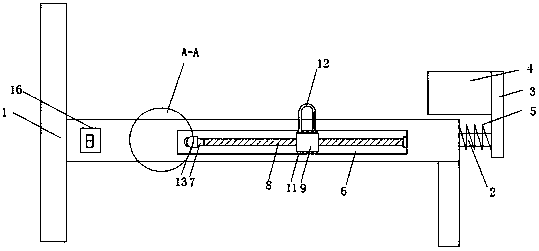
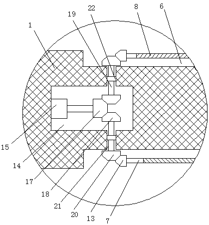
[0020] Example: Reference Figure 1-4 In this embodiment, a patient’s lower limb function self-rehabilitation training bed is proposed, including a bed body 1, two slide bars 2 are slidably connected to the end of the bed body 1, and the two slide bars 2 are far away from one end of the bed body 1 The same vertical plate 3 is welded, and the top of the vertical plate 3 close to the bed body 1 is welded with a foot pedal 4, and the foot pedal 4 is located above the bed body 1, and both sides of the bed body 1 are provided with adjustment grooves 6 , and the top inner wall and the bottom inner wall of the adjustment groove 6 are provided with raceways, the inner wall of the adjustment groove 6 near the end of the bed 1 is rotated and installed with a rotating shaft 7, and the outer thread of the rotating shaft 7 is equipped with a movable seat 9. The movable seat 9 is provided with a threaded through hole 10, and the threaded through hole 10 is engaged with an arc-shaped thread ...


PUM


Abstract

The invention discloses a self-rehabilitation training bed for the lower limb function of a patient. The training bed comprises a bed body, two sliding rods are slidingly connected to the bed end sideof the bed body, and a same vertical plate is welded to the ends, away from the bed body, of the two sliding rods; a pedal plate is welded to the top of the side, close to the bed body, of the vertical plate, the pedal plate is located above the bed body, and adjusting grooves are formed in two sides of the bed body; rolling ways are formed in the inner walls of the tops and the bottoms of the adjusting grooves, rotation shafts are rotatably mounted on the inner walls of the sides, close to the bed end of the bed body, of the adjusting grooves, and movable bases are mounted on the outer sidesof the rotation shafts in a threaded mode; multiple balls which are connected with the rolling ways in a rolling mode are embedded in the tops and the bottoms of the movable bases, and U-shaped armrests are welded to the sides of the tops, away from each other, of the two movable bases. The self-rehabilitation training bed is economic and practical, the positions of the U-shaped armrests can be adjusted according to patients with different heights, and the application range of the self-rehabilitation training bed for the suitable crowd is greatly broadened.

Description

technical field [0001] The invention relates to the technical field of autonomous rehabilitation training bed, in particular to an autonomous rehabilitation training bed for lower limb function of patients. Background technique [0002] At present, there are many cases of lower limb dysfunction and obstacles caused by sequelae of cerebrovascular disease, brain tumor, craniocerebral trauma, limb joint disease, etc. It will cause muscle atrophy, degeneration of motor function, and inability to take care of oneself. For such patients, self-physical function exercise on the auxiliary bed is very critical, so the patient's lower limb function independent rehabilitation training bed emerges as the times require. The existing patient's lower limb function independent rehabilitation training bed includes two slidingly installed The end of the two sliders away from the bed is welded with the same vertical plate, the top of the vertical plate close to the bed is welded with a foot pe...

Claims


Application Information

Patent Timeline
Patent Type & Authority Applications(China)
IPC IPC(8): A61H1/02
CPCA61H1/0218A61H1/0237A61H2201/0142A61H2201/1207A61H2201/14
Inventor 赵峰
Owner 陕西专壹知识产权运营有限公司
Why Eureka
Try Eureka