A crushing, screening and mixing machine

An all-in-one machine and screening layer technology, which is applied in the fields of filtration, solid separation, agricultural machinery and tools, etc., can solve problems such as unexisted

Active Publication Date: 2020-11-13
HARBIN INST OF TECH
View PDF5 Cites 0 Cited by
  • Summary
  • Abstract
  • Description
  • Claims
  • Application Information

AI Technical Summary

Problems solved by technology

[0005] In order to solve the problem that there is no device for processing straws that integrates crushing, screening and stirring in the prior art, the present invention provides a crushing, screening and stirring integrated machine. This device integrates crushing, screening and stirring, and can simultaneously realize The crushing, screening and stirring of straw do not need to be carried out separately, which greatly saves the production cost. The technical scheme adopted is:

Method used


Image

  • A crushing, screening and mixing machine

Examples


Embodiment approach 1

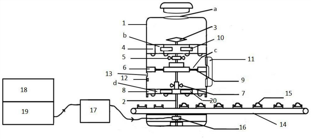
[0029] combine figure 1 -Description of this embodiment, a crushing, screening and stirring integrated machine of this embodiment, the integrated machine includes a body shell 1, and a transmission shaft 2 located inside the body shell 1, a crushing blade 3, a crushing layer bottom plate 4, a stirring paddle 15, Screening layer bottom plate 6, stirring paddle II7, stirring layer bottom plate 8 and filter screen 9; wherein: the top of the body shell 1 is provided with feeding port a; the crushing layer bottom plate 4, screening layer bottom plate 6 and stirring layer bottom plate 8 are It is fixedly connected to the inner wall of the body shell 1 from top to bottom; one end of the transmission shaft 2 is vertically fixed on the center of the bottom wall inside the body shell 1 through a bearing seat, and the end of the other end is fixedly connected to the crushing blade 3; The transmission shaft 2 passes through the stirring layer bottom plate 8, the screening layer bottom pla...

Embodiment approach 2

[0035] This embodiment adds a technical feature controllable passage 11 on the basis of Embodiment 1; the increased controllable passage 11 in this embodiment is located outside the body shell 1, and the entrance of the controllable passage is arranged on the crushing floor bottom plate 4 and the screening Between the bottom plates 6 of the layers, the outlet is arranged between the bottom plates of the screening layer 6 and the bottom plate of the stirring layer 8 .

[0036] The controllable channel 11 of this embodiment connects the screening layer with the stirring layer, and is used to transport the large straw fragments left in the screening layer to the stirring layer through the controllable channel 11, where they are processed by stirring and mixed with other raw materials. (such as glue and / or water), prepared as an intermediate material that requires large-grain straw raw material products.

Embodiment approach 3

[0038] In this embodiment, the technical feature conveyor belt 14 is added on the basis of the first or second embodiment; Inside out.

[0039] The conveyor belt 14 in this embodiment corresponds to the exit position of the material channel IIId, so that the falling materials fall onto the conveyor belt under the action of gravity.

[0040] The conveyor belt 14 added in this embodiment can realize the conveyance of materials, and convey the materials to the next process device.

[0041] The conveyor belt in this embodiment is used to transport materials, and the conveyor belt 14 is an existing product, mainly composed of crawler belts, pulleys and other parts.


PUM


Abstract

The invention discloses a crushing, screening and stirring integrated machine, and belongs to the field of biomass processing equipment. The integrated machine includes a machine body shell, a transmission shaft, a crushing blade, a crushing layer bottom plate, a stirring paddle I, a screening layer bottom plate, a stirring paddle II, a stirring layer bottom plate, filter nets and controllable switches; the crushing layer bottom plate, the screening layer bottom plate and the stirring layer bottom plate are sequentially and fixedly connected with the inner wall of the machine body shell from the top to the bottom; one end of the transmission shaft is vertically fixed on the center of the bottom wall in the machine body shell through a bearing seat, and the end part of the other end is fixedly connected with the crushing blade; the transmission shaft sequentially passes through the stirring layer bottom plate, the screening layer bottom plate and the crushing layer bottom plate from thebottom to the top; and the stirring paddle I and the stirring paddle II are fixedly connected with the transmission shaft. The integrated machine provided by the invention can separate particles withdifferent sizes, so that the time consumed by production of two raw materials is saved and the energy is saved to a certain extent; and the integrated machine realizes reasonable utilization of spaceand saves the energy consumed by operation of a plurality of large-scale machinery.

Description

technical field [0001] The invention relates to a crushing, screening and mixing integrated machine, which belongs to the field of biomass processing equipment. Background technique [0002] According to relevant statistics, my country, as a large agricultural country, can produce more than 700 million tons of straw every year, only about 10%-15% of which is utilized. In this case, if it is completely handled by farmers, there will be a large number of incineration. Every year during the summer harvest and autumn and winter, a large amount of straw is always burned in the fields, resulting in a large amount of dense fog and causing the "greenhouse effect". [0003] Straw is mostly used for burning, which is a major source of environmental pollution. According to data, when straw is burned, the three pollution indexes of sulfur dioxide, nitrogen dioxide, and inhalable particulate matter in the atmosphere reach their peaks, and the concentration of sulfur dioxide is higher th...

Claims


Application Information

Patent Timeline
Patent Type & Authority Patents(China)
IPC IPC(8): A01F29/00A01F29/14B07B1/04B07B1/42B07B1/46
CPCA01F29/005A01F29/14B07B1/04B07B1/42B07B1/4609B07B2201/04
Inventor 帅永吴志宏庞松健崔云峰张浩靳博越侯宗昇潘庆辉
Owner HARBIN INST OF TECH
Why Eureka
Try Eureka