Energy-saving roof structure and use method thereof
A roof structure and roof panel technology, applied in the direction of roof, roof ventilation, roof drainage, etc., can solve the problems of energy-saving roofs, such as large water consumption and external environmental impact, to achieve stable cooling effect, solve large water consumption, and reduce roof temperature. Effect
- Summary
- Abstract
- Description
- Claims
- Application Information
AI Technical Summary
Problems solved by technology
Method used
Image
Examples
Embodiment 1
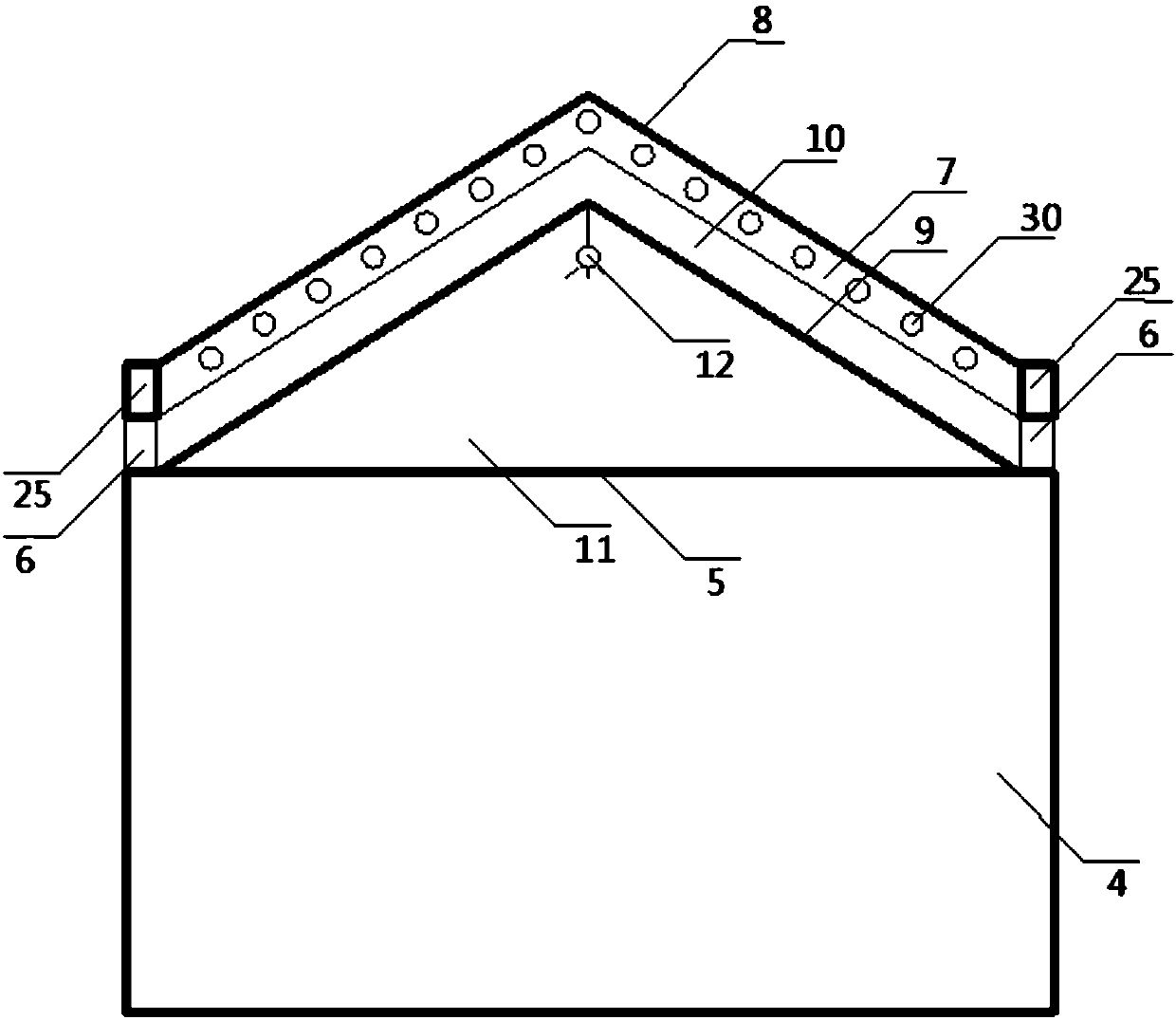
[0041] refer to figure 1 and figure 2 , an energy-saving roof structure provided by this embodiment is arranged on the top of a building body with an air-conditioning system, and the air-conditioning system includes an air conditioner 1 for adjusting the temperature inside the building body 4, a heat exchanger 2, and a water collection tank 3 , the outdoor air enters the interior 4 of the main body of the building after being heat-exchanged by the heat exchanger 2, and then is discharged from the interior 4 of the main body of the building through the heat exchange device of the heat exchanger 2, and the condensed water of the air conditioner 1 is discharged into the water collection tank 3;
[0042]The energy-saving roof structure includes a roof panel 5, a support frame 7, and a roof panel 8. The support frame 7 is arranged above the roof panel 5, and the roof panel 8 is laid above the support frame 7;
[0043] A partition 9 is also arranged above the roof panel 5, and the...
Embodiment 2
[0050] refer to Figure 2 to Figure 4 , on the basis of Embodiment 1, the present embodiment also includes an eave cover plate, and the eave cover plate includes an upper cover plate 17, an outer cover plate 18, an inner cover plate 19, one side of the upper cover plate 17 and an outer cover plate 18 are closed and connected, the other side of the upper cover 17 is provided with a raised flange 20, the shape of the inner cover 19 matches the protrusion of the flange 20, and there is a gap between the flange 20, Filter screen 22 is set in the gap, and water storage tank 23 is set in the middle part of inner cover plate 19, and described flange 20 stretches into water storage tank 23 and does not contact with the bottom of water storage tank 23, and the outside of water storage tank 23 is provided with drainage tank 24;
[0051] The eaves cover plate is arranged on the top of the air passage 6, and forms the eaves cavity 25 with the upper surface of the air passage 6, and a vent...
Embodiment 3
[0058] refer to Figure 3 to Figure 5 In this embodiment, on the basis of Embodiment 2, in the energy-saving roof structure, in order to improve the heat dissipation effect, the roof panels 8 are two pieces, which are distributed in a "eight" shape, and the height of one roof panel 8 is slightly higher On another roof board 8, an upper vent is formed between the tops of the two roof boards, and a dust filter 29 is arranged at the upper vent. Windows can also be set on the outside of the dust filter net 29 to adjust the size of the ventilation.
[0059] As a preferred embodiment, in order to have a better ventilation effect, in the energy-saving roof structure, the height of the ventilation channel 6 is 15-20 cm.
[0060] As a preferred embodiment, in order to make full use of energy, the material of the roof board 8 is BIPV, and for better heat preservation, the partition 9 is an EPS foam partition.
PUM
 Abstract
Description
Claims
Application Information
 - R&D
- Intellectual Property
- Life Sciences
- Materials
- Tech Scout
- Unparalleled Data Quality
- Higher Quality Content
- 60% Fewer Hallucinations
Browse by: Latest US Patents, China's latest patents, Technical Efficacy Thesaurus, Application Domain, Technology Topic, Popular Technical Reports.
© 2025 PatSnap. All rights reserved.Legal|Privacy policy|Modern Slavery Act Transparency Statement|Sitemap|About US| Contact US: help@patsnap.com


