
Aerial camera capable of safely landing

A technology for safe landing and aerial photography, which is applied in the field of aerial photography, can solve problems such as the damage of aerial photography and the lack of shock-absorbing tripod of the aerial photography, and achieve the effect of ensuring safe landing, protecting safe landing, and ensuring safe landing.

Inactive Publication Date: 2018-03-02
成都鑫晨航空科技有限公司
View PDF0 Cites 2 Cited by
  • Summary
  • Abstract
  • Description
  • Claims
  • Application Information

AI Technical Summary

Problems solved by technology

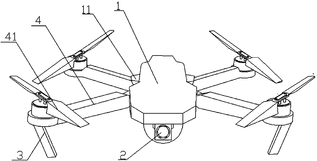
[0003] The present invention provides an aerial camera that is easy to land, which solves the problem that the aerial camera in the prior art does not have a shock-absorbing tripod, and improper landing easily causes damage to the aerial camera

Method used


Image

  • Aerial camera capable of safely landing
  • Aerial camera capable of safely landing
  • Aerial camera capable of safely landing

Examples


Embodiment 1

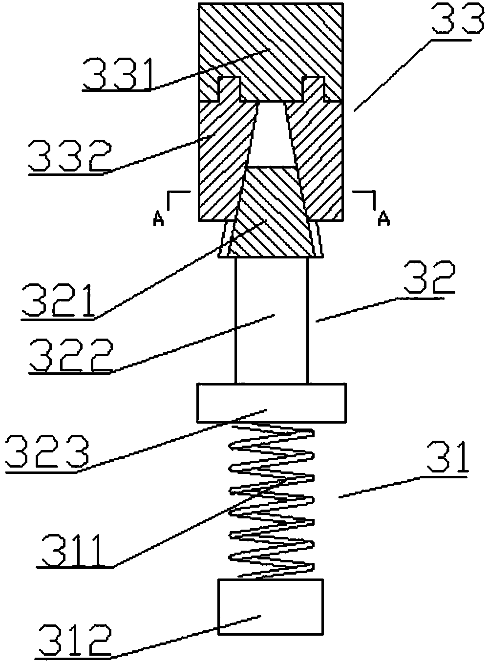
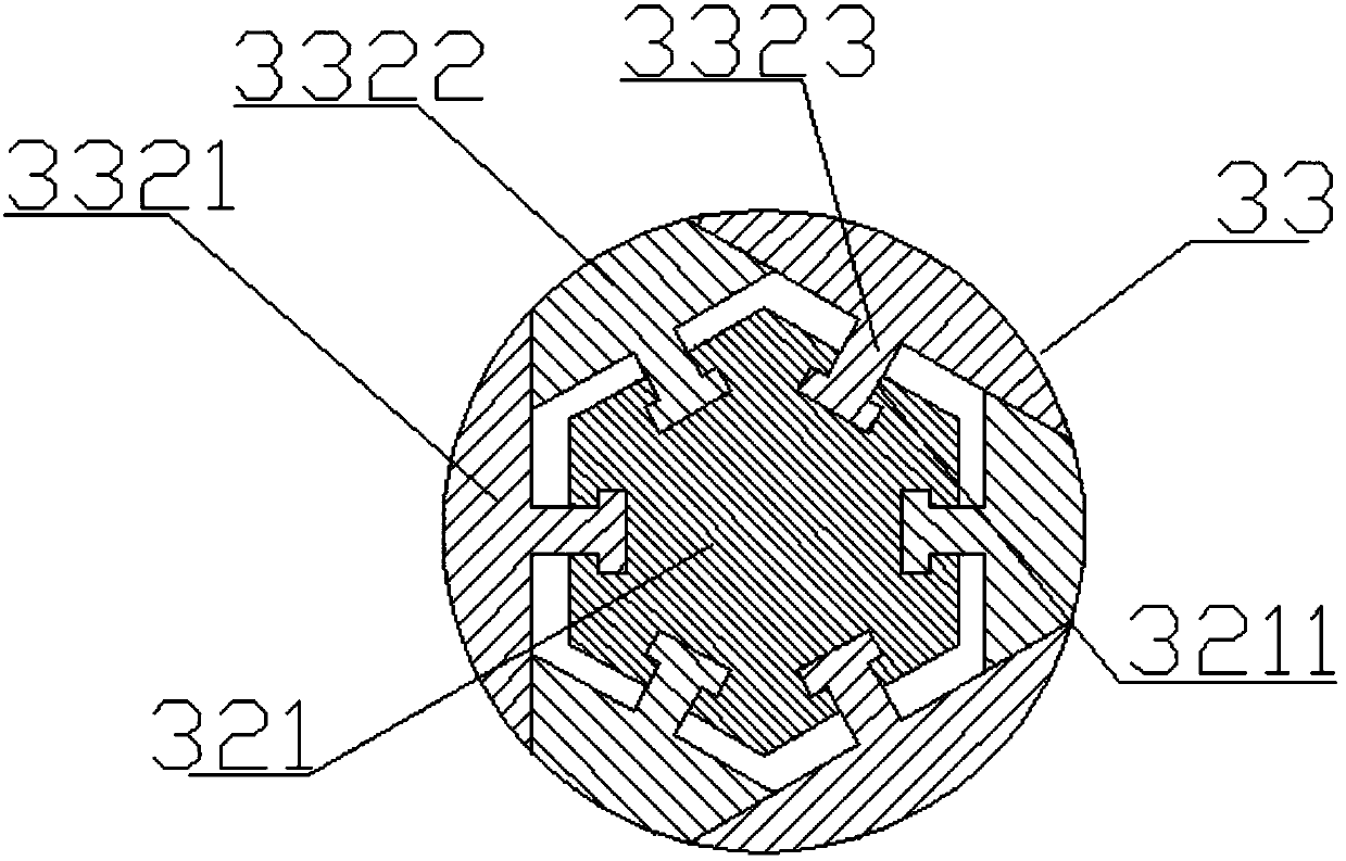
[0026] An aerial camera that ensures safe landing, comprising an aerial camera body 1 and a camera 2 arranged at the bottom of the aerial camera body, characterized in that: multiple groups of shock-absorbing tripods 3 are arranged under the aerial camera body 1, and the shock-absorbing The tripod 3 includes a primary damping device 31, an intermediate connector 32, and a secondary shock absorbing device 33 connected sequentially from bottom to top, and is characterized in that: the secondary shock absorbing device 33 includes a top that is connected to the drone body 1 Connecting piece 331, the top connecting piece 331 is cylindrical, the bottom surface of the top connecting piece 331 is provided with three expansion components 3321 along the circumferential direction, the expansion components 3321 are provided with connecting components 3322 between two, said The expansion assembly 3321 and the connection assembly 3322 form a shock absorber 332, one end of the intermediate co...

Embodiment 2

[0028] The shock absorbing head 321 is in the shape of a regular hexagonal pyramid, and each side of the shock absorbing head 321 is provided with a T-shaped groove 3211 .

Embodiment 3

[0030] The outer edge of the shock-absorbing sleeve 332 in an unstretched state forms a cylinder, and the inner edge of the shock-absorbing sleeve 332 in an unexpanded state forms a hexagonal pyramidal groove for the shock-absorbing head 321 to fit. A T-shaped protrusion 3323 matching the T-shaped groove 3211 is provided on each side of the groove corresponding to the shock-absorbing head 321 .


PUM


Abstract

The invention discloses an aerial camera capable of safely landing. The aerial camera comprises an aerial camera body and a camera arranged at the bottom portion of the aerial body, wherein plural groups of vibration reducing foot frames are arranged below the aerial camera body, the vibration reducing foot frame comprises a first-stage vibration reducing device, a middle connection member and a second-stage vibration reducing device, the second-stage vibration reducing device comprises a top portion connection member, the top portion connection member is cylindrical, the bottom surface of thetop portion connection member is provided with three expansion assemblies, connection assemblies are arranged between the two expansion assemblies, the expansion assembly and the connection assemblyform a vibration reducing sleeve, one end of the middle connection member is connected to the first-stage vibration reducing device, and the vibration reducing head on the other end of the middle connection member is sleeved in the vibration reducing sleeve and can move along the axial direction of the vibration reducing sleeve. According to the present invention, the vibration reducing foot frameis arranged into the first-stage vibration reducing device and the second-stage vibration reducing device, and the second-stage vibration reducing device uses the vibration reducing sleeve to coat the vibration reducing head, such that the vibration reducing is performed on the landing through different structures, the problem of too high impact force during the landing is well solved, and the safe landing of the aerial camera is ensured.

Description

technical field [0001] The invention relates to the field of aerial photography devices, in particular to an aerial photography device that ensures safe landing. Background technique [0002] Aerial photography, also known as aerial photography or aerial photography, refers to taking pictures of the earth's landforms from the air to obtain a top view. This picture is an aerial photo. At present, most of the aerial photography is to install the camera on the aerial photography device, and to shoot the desired image by controlling the flight path of the aerial photography device. Aerial cameras are well used in many places, such as: water conservancy and hydrological observation, TV program recording, etc., and even in some important celebrations, aerial cameras have appeared; the existing aerial cameras do not have shock-absorbing tripods, landing It is necessary to choose a softer terrain when landing, and improper landing may easily cause damage to the drone. Contents of...

Claims


Application Information

Patent Timeline
Patent Type & Authority Applications(China)
IPC IPC(8): B64C25/58B64C25/62B64C27/08
CPCB64C25/58B64C25/62B64C27/08
Inventor 石存岭
Owner 成都鑫晨航空科技有限公司
Learn More