
Lamination fixture and laser cutting system

A film system and laser cutting technology, used in laser welding equipment, manufacturing tools, metal processing equipment, etc., can solve the problem of large loss of film substrates, and achieve the effect of reducing overall cost, improving economy, and improving cutting accuracy

Active Publication Date: 2020-06-16
ZHANGJIAGANG KANGDE XIN OPTRONICS MATERIAL
View PDF11 Cites 0 Cited by
  • Summary
  • Abstract
  • Description
  • Claims
  • Application Information

AI Technical Summary

Problems solved by technology

[0004] The main purpose of the present invention is to provide a film laminating fixture and laser film cutting system to solve the problem of large loss of film substrate in the process of film pasting of display screens in the prior art

Method used


Image

  • Lamination fixture and laser cutting system
  • Lamination fixture and laser cutting system
  • Lamination fixture and laser cutting system

Examples


Embodiment Construction

[0031] The technical solutions in the embodiments of the present invention will be clearly and completely described below in conjunction with the accompanying drawings in the embodiments of the present invention. Obviously, the described embodiments are only a part of the embodiments of the present invention, rather than all the embodiments. The following description of at least one exemplary embodiment is actually only illustrative, and in no way serves as any limitation to the present invention and its application or use. Based on the embodiments of the present invention, all other embodiments obtained by those of ordinary skill in the art without creative work shall fall within the protection scope of the present invention.

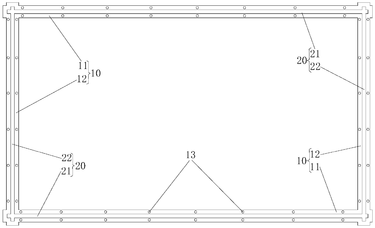
[0032] In order to solve the problem of large loss of the film substrate during the filming operation of the display in the prior art, the present invention provides a film pressing jig and a laser film cutting system; image 3 As shown, the lamination jig...


PUM

PropertyMeasurementUnit
widthaaaaaaaaaa
widthaaaaaaaaaa

Abstract

The invention provides a film pressing fixture and a laser film cutting system. The film pressing fixture comprises a frame body which is installed on a surface of film base material; the frame body is provided with an annular cutting path which is a light transmitting slit opened in the frame body; the light transmitting slit penetrates the frame body in the direction vertical to a plane surrounded by the frame body so that the laser penetrates and the film base material is cut on a display screen. The invention solves the problem that the film base material has a large amount of loss duringthe filming operation of the display screen in the prior art.

Description

Technical field [0001] The present invention relates to the technical field of laser cutting, in particular to a film pressing jig and a laser cutting system. Background technique [0002] In the field of display technology, the display screen is usually attached with a protective film, a polarizer or an explosion-proof film. The above-mentioned film materials are all in the form of a sheet. In order to ensure the precision of the display screen, the filming process of first sticking and cutting is usually adopted , That is, first pull out a certain length of the film substrate in a roll shape and directly attach it to the display glass. At this time, the display glass is completely covered by the film substrate, and then use the laser cutting process to cut the film substrate from the film substrate. It is equipped with a film substrate the size of the glass of the display screen as the above-mentioned protective film, polarizer or explosion-proof film. [0003] In the process of...

Claims


Application Information

Patent Timeline
Patent Type & Authority Patents(China)
IPC IPC(8): B23K26/38B23K26/70B23K26/402
CPCB23K26/38B23K26/402B23K26/702
Inventor 李锋褚福川
Owner ZHANGJIAGANG KANGDE XIN OPTRONICS MATERIAL
Learn More