Spaceborne Antenna Deployment Arm Device for Built-in Routing of RF Cables

A radio frequency cable and spaceborne antenna technology, which is applied in the field of spaceborne antenna deployment arm devices, can solve problems such as poor aesthetics, weight reduction design, unfavorable products, etc. Good for wiring

Active Publication Date: 2019-09-17
SHANGHAI SATELLITE ENG INST
View PDF5 Cites 0 Cited by
  • Summary
  • Abstract
  • Description
  • Claims
  • Application Information

AI Technical Summary

Problems solved by technology

[0002] Conventional space-borne antennas that need to be deployed on the orbit usually adopt external routing for the RF cable in order to facilitate disassembly and assembly of the product on the ground. This design method has some shortcomings. First, when the cable is long, it needs to be installed on the deployment arm Cable clamps; 2. The exposed cables need additional thermal control protection to adapt to the temperature environment on orbit; 3. It is not conducive to the weight reduction design of the entire product; 4. There is a risk of hooking in the exposed cables during the unfolding process, which needs to be considered Anti-hook design; 5. The appearance of the product is not good. The expansion arm design with built-in cable wiring can avoid the above shortcomings. The built-in clamp plays a role in fixing the cable to prevent the cable from shaking. Additional thermal control coating is required, and the thermal control layer can be shared with the deployment arm. After the built-in cable eliminates the risk of cable hooking during the deployment process, the appearance of the entire product is neat after the cable is built-in

Method used


Image

  • Spaceborne Antenna Deployment Arm Device for Built-in Routing of RF Cables
  • Spaceborne Antenna Deployment Arm Device for Built-in Routing of RF Cables
  • Spaceborne Antenna Deployment Arm Device for Built-in Routing of RF Cables

Examples


Embodiment Construction

[0021] The present invention will be described in detail below in conjunction with specific embodiments. The following examples will help those skilled in the art to further understand the present invention, but do not limit the present invention in any form. It should be noted that those skilled in the art can make several modifications and improvements without departing from the concept of the present invention. These all belong to the protection scope of the present invention.

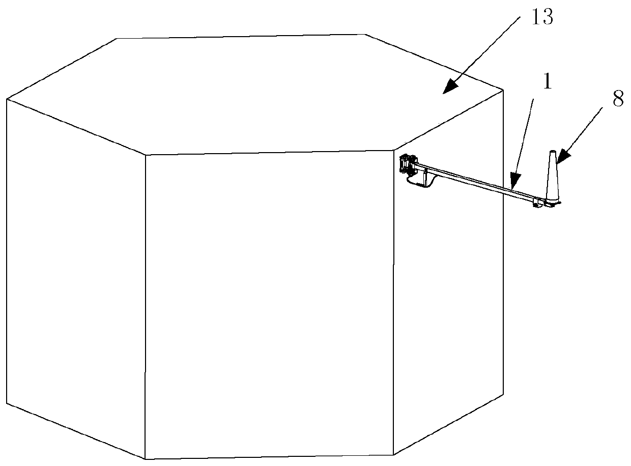
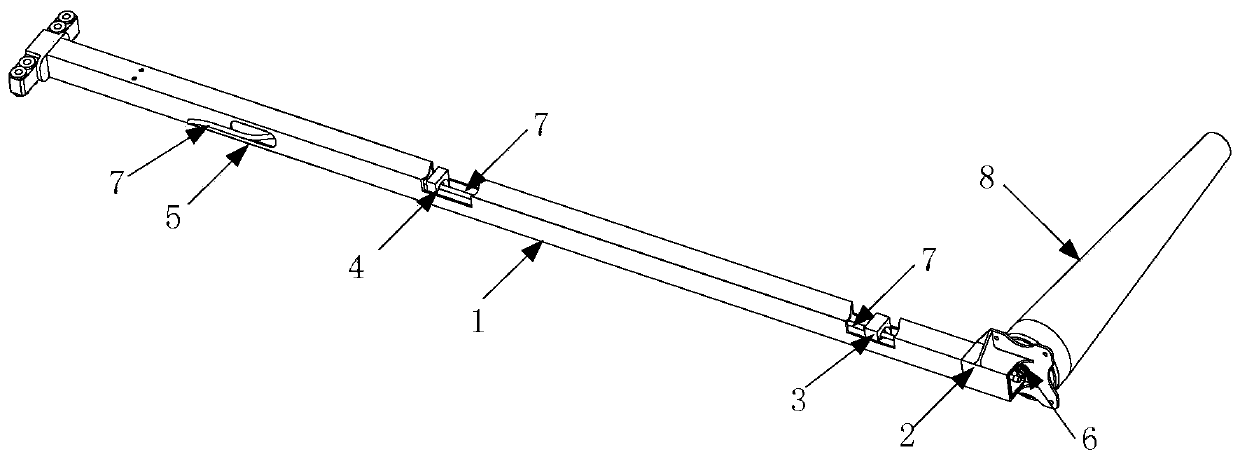
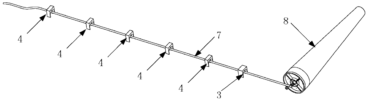
[0022] Such as figure 1 As shown, the present invention can realize the radio frequency cable built-in wiring space-borne antenna deployment arm device, including the deployment rod 1, the antenna mounting bracket 2, the head end clamp 3, the middle clamp 4, and the deployment rod 1 is a rectangular or circular hollow inside. Rod member, at least one radio frequency cable 7 is inserted into the deployment rod 1 through an installation opening 6 of the antenna mounting bracket 2, passes through the...


PUM


Abstract

The invention provides a satellite-borne antenna unfolding arm device capable of achieving built-in wiring of a radio-frequency cable. The satellite-borne antenna unfolding arm device comprises an unfolding rod, an antenna installing support, a head end clamping hoop and middle clamping hoops, wherein the unfolding rod is an internally hollow rectangular or round rod, at least one radio-frequencycable penetrates into the unfolding rod from one installation opening of the antenna installing support and sequentially penetrates through the head end clamping hoop and the multiple middle clampinghoops to extend out of an extending hole formed in the unfolding rod, a connector assembly of the radio-frequency cable is connected with one antenna at the installation opening, and at least one binding belt penetrates into the head end clamping hoop and fixes the radio-frequency cable to the inner wall of the unfolding rod. The satellite-borne antenna unfolding arm device achieves an internal wiring function of the antenna radio-frequency cable. The satellite-borne antenna unfolding arm device is conductive to wiring of cables outside a cabin, the product weight is reduced, the possibility that the cables outside the cabin hooks movable parts is reduced, and integrated thermal control design of an unfolding arm and the radio-frequency cable is facilitated.

Description

technical field [0001] The invention relates to a spaceborne antenna deployment arm device, in particular to a spaceborne antenna deployment arm device capable of realizing built-in wiring of radio frequency cables. Background technique [0002] Conventional space-borne antennas that need to be deployed on the orbit, in order to facilitate the disassembly and assembly of the product on the ground, usually use external routing for its RF cables. This design method has some shortcomings. First, when the cable is long, it needs to be installed on the deployment arm Cable clamps; 2. The exposed cables need additional thermal control protection to adapt to the temperature environment on-orbit; 3. It is not conducive to the weight reduction design of the entire product; 4. There is a risk of hooking during the unfolding process of the exposed cables, which needs to be considered Anti-hook design; 5. The appearance of the product is not good. The deployment arm design with built-in...

Claims


Application Information

Patent Timeline
Patent Type & Authority Patents(China)
IPC IPC(8): H01Q1/10
Inventor 张如变王涵杨杜赵晋丁菲张玉山袁荣刚郑京良
Owner SHANGHAI SATELLITE ENG INST
Why Eureka
Try Eureka