
Rearview mirror for narrowing blind area

A rearview mirror and blind spot technology, which is applied in the field of rearview mirrors, can solve the problems of inconvenient vehicles and vehicles, inconvenience of driving vehicles, hidden dangers of vehicle safety, etc., to achieve the effect of easy disassembly and installation, reducing the risk of driving, and reducing potential safety hazards

Inactive Publication Date: 2018-02-27
白皓
View PDF5 Cites 5 Cited by
  • Summary
  • Abstract
  • Description
  • Claims
  • Application Information

AI Technical Summary

Problems solved by technology

[0004] The purpose of the present invention is to provide a kind of rearview mirror that reduces blind spot, to solve the original rearview mirror proposed in the above-mentioned background technology when the vehicle stops, static blind spot can be produced, and the reflected range of rearview mirror is limited at this moment, When there is an obstacle or a child in the blind spot, it cannot be found in time, which may cause safety hazards when driving the vehicle, thereby reducing the driver's field of vision. When the vehicle is driving, a dynamic blind spot will be produced. At this time, the rearview mirror can only Observing a certain range on both sides of the vehicle makes it difficult to judge the distance between vehicles when the vehicle is turning or overtaking, thereby increasing the safety hazard of driving, and it is not convenient to observe vehicles coming from a long distance during driving. Therefore, it is not convenient to make an effective choice during driving. In rainy and snowy weather, the water droplets and frost and snow attached to the mirror surface of the original rearview mirror will also cause the driver's dazzling and blurred vision, which will cause inconvenience when driving the vehicle. question

Method used


Image

  • Rearview mirror for narrowing blind area
  • Rearview mirror for narrowing blind area
  • Rearview mirror for narrowing blind area

Examples


Embodiment Construction

[0019] The following will clearly and completely describe the technical solutions in the embodiments of the present invention with reference to the accompanying drawings in the embodiments of the present invention. Obviously, the described embodiments are only some, not all, embodiments of the present invention. Based on the embodiments of the present invention, all other embodiments obtained by persons of ordinary skill in the art without making creative efforts belong to the protection scope of the present invention.

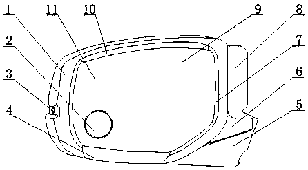
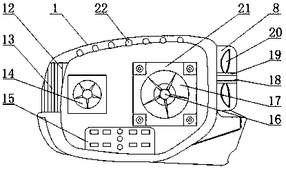
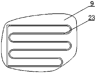
[0020] see Figure 1-7 , the present invention provides a technical solution: a rearview mirror for reducing blind spots, comprising a rearview mirror 1, a bearing 18 and a camera 24, the right end of the rearview mirror 1 is provided with a fixed rod 6, and the bottom of the fixed rod 6 is provided with a mounting Arm 5, the upper right side of rearview mirror 1 is provided with fan 8, and the left middle position of rearview mirror 1 is provided with warning...


PUM


Abstract

The invention discloses a rearview mirror for narrowing a blind area. The rearview mirror comprises a rearview mirror body, a bearing and a camera, the right end of the rearview mirror body is provided with a fixing rod, a lower portion of the fixing rod is provided with an installation arm, the upper portion of the right side of the rearview mirror body is provided with a fan, the middle of the left side of the rearview mirror body is provided with a warning light, and the middle of the front surface of the rearview mirror body is provided with an eye-level lens; the rearview mirror body is provided with a circular mirror, and the circular mirror is adhesive to a magnifying lens through a sucker mounting ring on a fixing plate so that the circular mirror can be easy to disassemble and assemble; when a driver prepares to start a vehicle, the driver can clearly observe the conditions below the two sides of the vehicle by observing the circular mirror, so that when the vehicle begins todepart, the safety of pedestrians is ensured, and the hidden safety hazards are reduced; the eye-level lens and the magnifying lens are arranged on the rearview mirror body, so that when the vehicle runs, the distance between vehicles can be effectively judged by observing the magnifying lens.

Description

technical field [0001] The invention belongs to the technical field of rearview mirrors, in particular to a rearview mirror for reducing blind spots. Background technique [0002] The rearview mirror is a tool for the driver to directly obtain external information such as the rear, side and bottom of the car while sitting in the cab seat. Rearview mirrors must be installed, and all rearview mirrors must be able to adjust the direction. Rearview mirrors have a problem of vision, that is, the range that the mirror surface can reflect. The industry has a formulation of three elements of vision, that is, the driver's eyes The distance from the rearview mirror, the size of the rearview mirror and the radius of curvature of the rearview mirror have a certain relationship between these three elements. When the distance and size of the rearview mirror are the same, the smaller the radius of curvature of the mirror surface, the smaller the radius of curvature of the mirror surface. ...

Claims


Application Information

Patent Timeline
Patent Type & Authority Applications(China)
IPC IPC(8): B60R1/06B60R1/08B60R1/12
Inventor 白皓
Owner 白皓
Learn More