Rotary type display device for illumination lamp

A display device and rotating technology, which is applied in the field of rotating display devices for lighting lamps, can solve the problems affecting the sales of lighting lamps, rigid display of lighting lamps, lack of interest, etc.

Active Publication Date: 2018-02-27
SEESA HLDG
View PDF9 Cites 12 Cited by
  • Summary
  • Abstract
  • Description
  • Claims
  • Application Information

AI Technical Summary

Problems solved by technology

[0003] When the current lighting fixtures are sold in the store, the lighting fixtures are directly fixed on the wall, and then the lighting fixtures are energized to light up the lighting fixtures for display. There is not much interest, thus affecting the sales of lighting fixtures
[0004] Therefore, there is an urgent need to develop a rotating display device for lighting that not only fixes the lighting fixture, but also rotates the lighting fixture displayed, so as to overcome the lack of interest in the prior art by directly fixing the lighting fixture on the wall for display. shortcoming

Method used


Image

  • Rotary type display device for illumination lamp
  • Rotary type display device for illumination lamp
  • Rotary type display device for illumination lamp

Examples


Embodiment 1

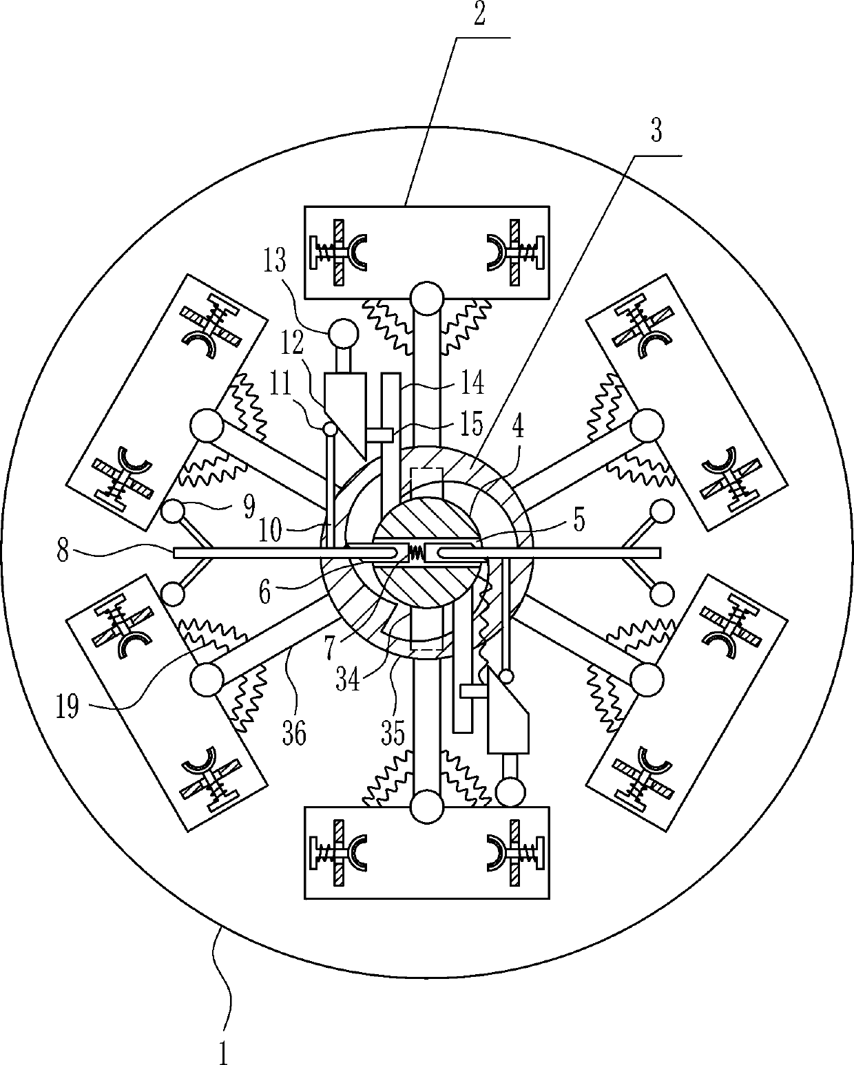
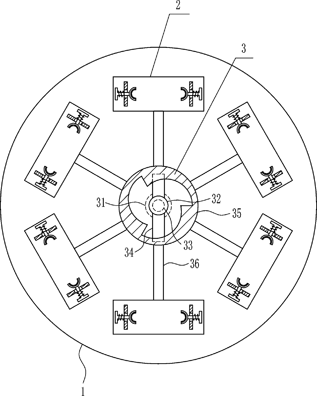
[0030] A rotating display device for lighting, such as Figure 1-5 As shown, it includes a mounting plate 1, a clamping mechanism 2 and a rotating mechanism 3. The mounting plate 1 is installed on the wall, the middle part of the mounting plate 1 is connected with a rotating mechanism 3, and the outer ends of the rotating mechanism 3 are connected with a clamping mechanism 2.

Embodiment 2

[0032] A rotating display device for lighting, such as Figure 1-5 As shown, it includes a mounting plate 1, a clamping mechanism 2 and a rotating mechanism 3. The mounting plate 1 is installed on the wall, the middle part of the mounting plate 1 is connected with a rotating mechanism 3, and the outer ends of the rotating mechanism 3 are connected with a clamping mechanism 2.

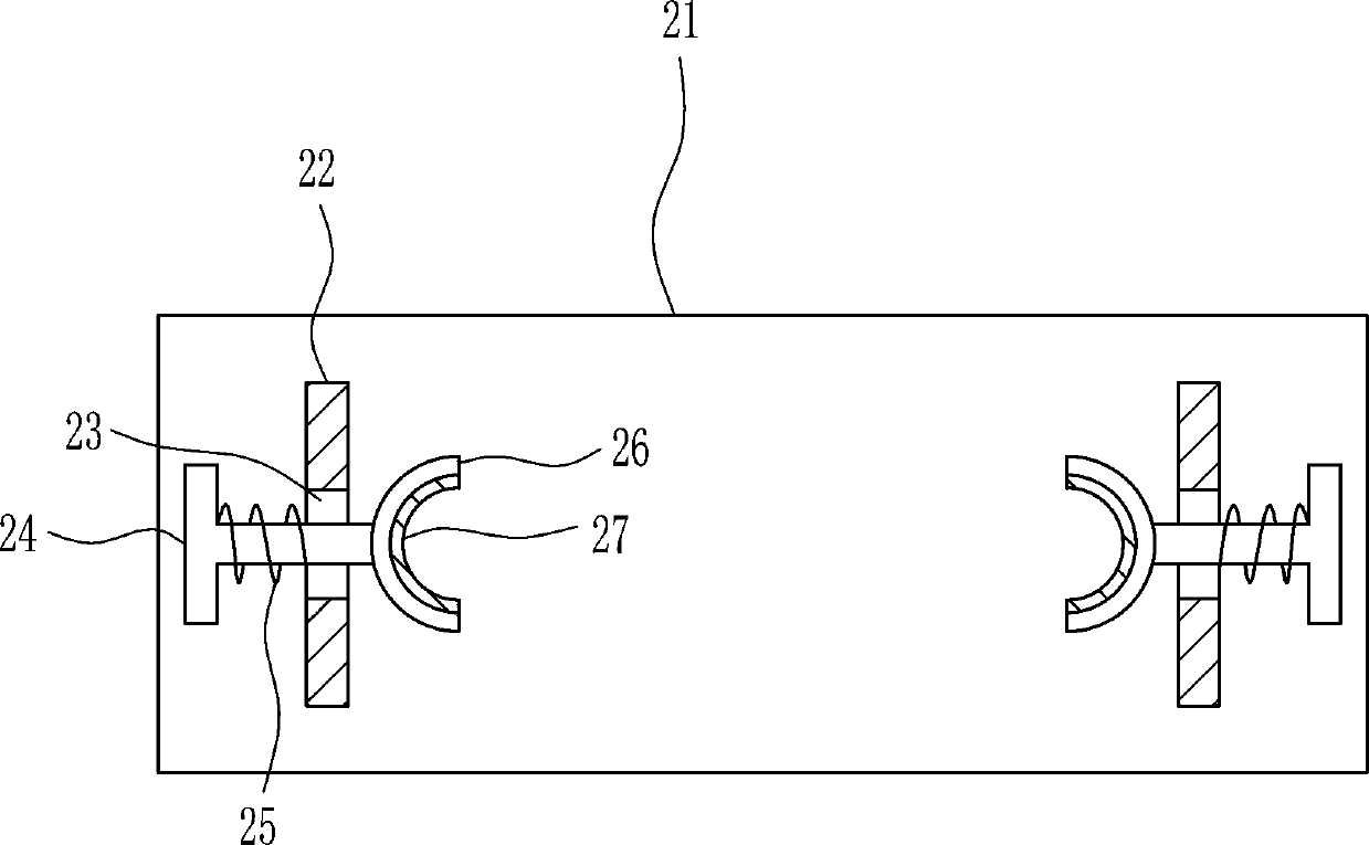
[0033]Clamping mechanism 2 comprises fixed plate 21, fixed rod 22, pull bar 24, first spring 25, clamp bar 26 and rubber pad 27, and rotating mechanism 3 outer ends are all connected with fixed plate 21, and the left and right sides of fixed plate 21 front wall The sides are symmetrically connected with fixed rods 22, and the middle parts of the fixed rods 22 are provided with through holes 23. The outer middle parts of the fixed rods 22 are connected with the first springs 25, and the outer ends of the first springs 25 are connected with pull rods 24. Passing through the first spring 25 and the through...

Embodiment 3

[0035] A rotating display device for lighting, such as Figure 1-5 As shown, it includes a mounting plate 1, a clamping mechanism 2 and a rotating mechanism 3. The mounting plate 1 is installed on the wall, the middle part of the mounting plate 1 is connected with a rotating mechanism 3, and the outer ends of the rotating mechanism 3 are connected with a clamping mechanism 2.

[0036] Clamping mechanism 2 comprises fixed plate 21, fixed rod 22, pull bar 24, first spring 25, clamp bar 26 and rubber pad 27, and rotating mechanism 3 outer ends are all connected with fixed plate 21, and the left and right sides of fixed plate 21 front wall The sides are symmetrically connected with fixed rods 22, and the middle parts of the fixed rods 22 are provided with through holes 23. The outer middle parts of the fixed rods 22 are connected with the first springs 25, and the outer ends of the first springs 25 are connected with pull rods 24. Passing through the first spring 25 and the throug...


PUM


Abstract

The invention relates to a display device, in particular to a rotary type display device for an illumination lamp. The rotary type display device for the illumination lamp achieves the technical purpose that the illumination lamp can be fixed so that the displayed illumination lamp can rotate. In order to achieve the technical purpose, the rotary type display device for the illumination lamp comprises an installing plate and the like; the installing plate is installed on a wall, a rotating mechanism is connected to the middle of the installing plate, and a clamping mechanism is connected to the outer end of the rotating mechanism. By arranging the rotary type display device for the illumination lamp, a rubber gasket is arranged to achieve the effect of protecting the illumination lamp; byarranging the rotating mechanism, the rotary illumination lamp has more interestingness compared with an illumination lamp fixed to a wall, and the attention of a consumer is attracted; by arranging atransparent cover, the phenomenon that dust enters a machine when the device is operated is avoided, and therefore the service life of the devices is prolonged.

Description

technical field [0001] The invention relates to a display device, in particular to a rotating display device for lighting lamps. Background technique [0002] The role of lighting fixtures is not limited to lighting, but also the eyes of the home, more often it plays a decorative role. Therefore, the choice of lighting fixtures is much more complicated. It not only involves safety and energy saving, but also involves many factors such as material, type, style and taste. A good lighting may become the soul of the decoration at once. [0003] When the current lighting fixtures are sold in the store, the lighting fixtures are directly fixed on the wall, and then the lighting fixtures are energized to light up the lighting fixtures for display. There is not much interest, which affects the sales of lighting fixtures. [0004] Therefore, there is an urgent need to develop a rotating display device for lighting that not only fixes the lighting fixture, but also rotates the ligh...

Claims


Application Information

Patent Timeline
IPC IPC(8): A47F7/00A47F5/05
CPCA47F5/05A47F7/00A47F2007/0085
Inventor 孙美王荣衔曾标其他发明人请求不公开姓名
Owner SEESA HLDG
Why Eureka
Try Eureka