
Test device and method for cooker ignition control board

An ignition control and testing device technology, applied in program control, general control system, electrical testing/monitoring, etc., can solve problems such as troublesome and inconvenient detection, low detection efficiency, human misjudgment, etc. convenient effect

Pending Publication Date: 2018-02-23
中山华帝电子科技有限公司
View PDF0 Cites 3 Cited by
  • Summary
  • Abstract
  • Description
  • Claims
  • Application Information

AI Technical Summary

Problems solved by technology

[0002] At present, when producing the ignition control board of the cooker, the circuit board manufacturer checks whether the function of the cooker controller is qualified by a completely manual method, which generally includes manually connecting the ignition needle, the gas solenoid valve, the ignition knob to the ignition control board of the cooker and turning on the power supply. , and then manually turn the ignition knob, manually observe whether the ignition needle is discharged, and manually observe whether the gas solenoid valve is in motion. This process has the disadvantages of low detection efficiency, many detection personnel, and human error. The gas solenoid valve is actually connected to the gas pipeline to realize the detection process of flame combustion and flame extinguishment, which is troublesome and inconvenient to detect

Method used


Image

  • Test device and method for cooker ignition control board
  • Test device and method for cooker ignition control board
  • Test device and method for cooker ignition control board

Examples


Embodiment Construction

[0041] The features of the present invention and other relevant features are described in further detail below through the embodiments, so as to facilitate the understanding of those skilled in the art:

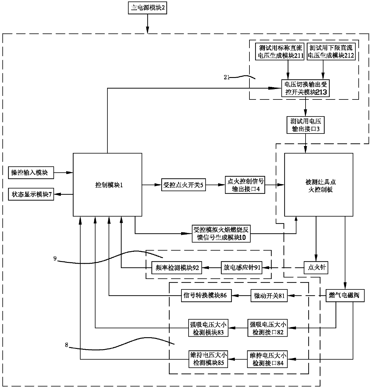
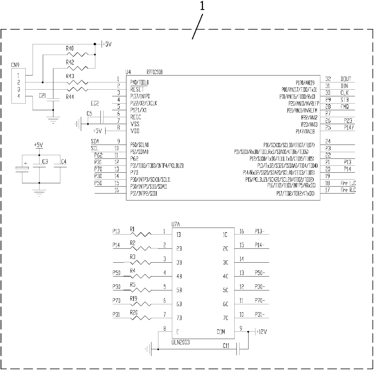
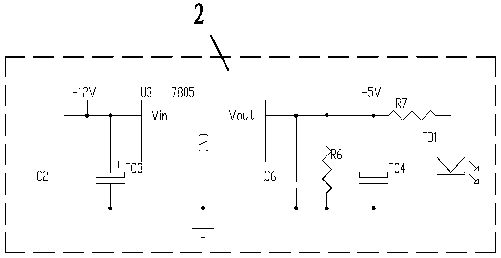
[0042] Such as figure 1 As shown, a test device for the ignition control board of the cooker includes a control module 1, a main power supply module 2 for the main power supply of the test device, and a test voltage for electrically connecting with the DC power input terminal of the ignition control board of the test cooker Output interface 3, an ignition control signal output interface 4 used to be electrically connected to the ignition control signal input end of the ignition control board of the cooking appliance under test, controlled by the control module 1 and used to output ignition control through the ignition control signal output interface 4 signal controlled ignition switch 5, the main power module 2 is connected with a test DC voltage generation module 21, and the...


PUM


Abstract

The invention discloses a test device and method for a cooker ignition control board. A control module controls a controlled simulated flame combustion feedback signal generation module to output simulated flame combustion feedback signals to a flame detection feedback connection end of the cooker ignition control board to be tested; then, an ignition needle state detection module is adopted to detect whether or not the cooker ignition control board to be tested can control an ignition needle to stop ignition after gas ignition is successful; after the controlled simulated flame combustion feedback signal generation module is controlled to stop outputting the simulated flame combustion feedback signals to the flame detection feedback connection end of the cooker ignition control board to be tested, a gas solenoid valve state detection module is adopted to detect whether or not the cooker ignition control board to be tested can control a gas solenoid valve to fall off and be switched off after gas flame is extinguished, so that the cooker ignition control board to be tested is safely detected, a test process in which the gas solenoid valve needs to be communicated with a gas pipeline to achieve the flame combustion and flame extinguishing is not involved during a test, and the test is more convenient.

Description

technical field [0001] The invention relates to a test device and a test method for an ignition control board of a cooker. Background technique [0002] At present, when producing the ignition control board of the cooker, the circuit board manufacturer checks whether the function of the cooker controller is qualified by a completely manual method, which generally includes manually connecting the ignition needle, the gas solenoid valve, the ignition knob to the ignition control board of the cooker and turning on the power supply. , and then manually turn the ignition knob, manually observe whether the ignition needle is discharged, and manually observe whether the gas solenoid valve is in motion. This process has the disadvantages of low detection efficiency, many detection personnel, and human error. The gas solenoid valve is really connected to the gas pipeline to realize the detection process of flame burning and flame extinguishing, which is troublesome and inconvenient t...

Claims


Application Information

Patent Timeline
IPC IPC(8): G05B23/02
CPCG05B23/0208G05B2219/24024
Inventor 吴泉李国兴邹文飞
Owner 中山华帝电子科技有限公司
Learn More