Angular contact ball bearing assembly fixture
A technology for angular contact ball bearings and assembly tooling, which is applied in bearing assembly, bearing, shaft installation, etc., and can solve problems such as low assembly efficiency
Active Publication Date: 2018-02-23
LUOYANG BEARING RES INST CO LTD
View PDF7 Cites 6 Cited by
- Summary
- Abstract
- Description
- Claims
- Application Information
AI Technical Summary
Problems solved by technology
[0003] The purpose of the present invention is to provide an angular contact ball bearing assembly tool to solve the problem of low assembly efficiency caused by the need for lubricants when assembling the existing tool
Method used
View moreImage
Smart ImageViewing Examples

Examples
specific Embodiment 6
[0027] Specific embodiment 6 of the angular contact ball bearing assembly tool of the present invention, in this embodiment, the material of the elastic support member can also be porous rubber, of course, it can also be ordinary rubber in other embodiments, and the others are the same as in embodiment 1 ,No longer.
Login to View More PUM
 Abstract
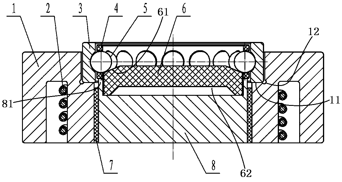
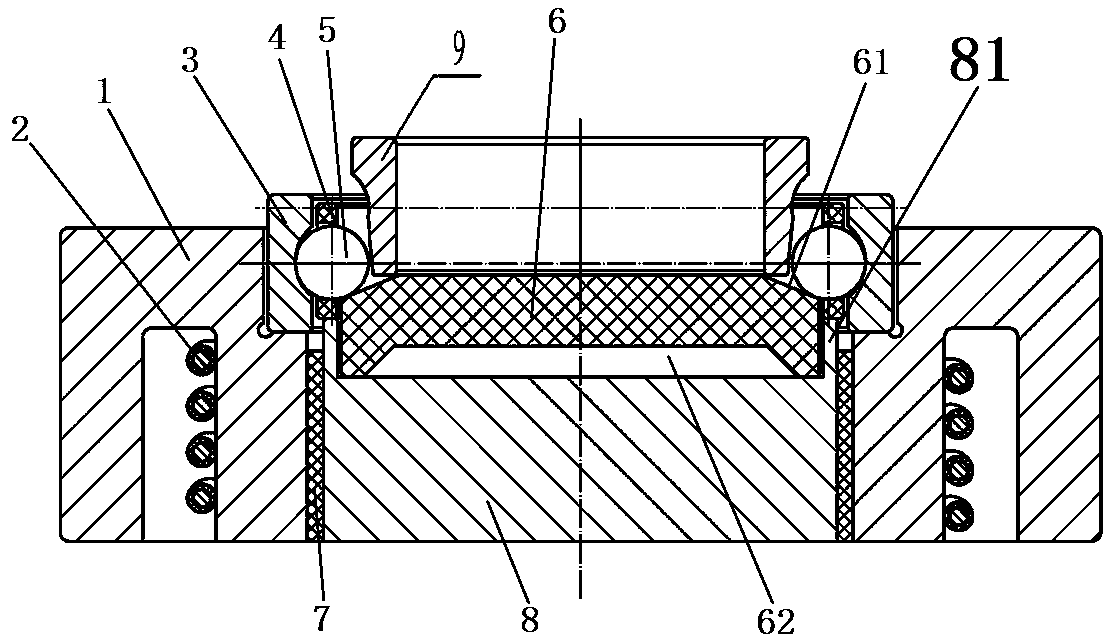
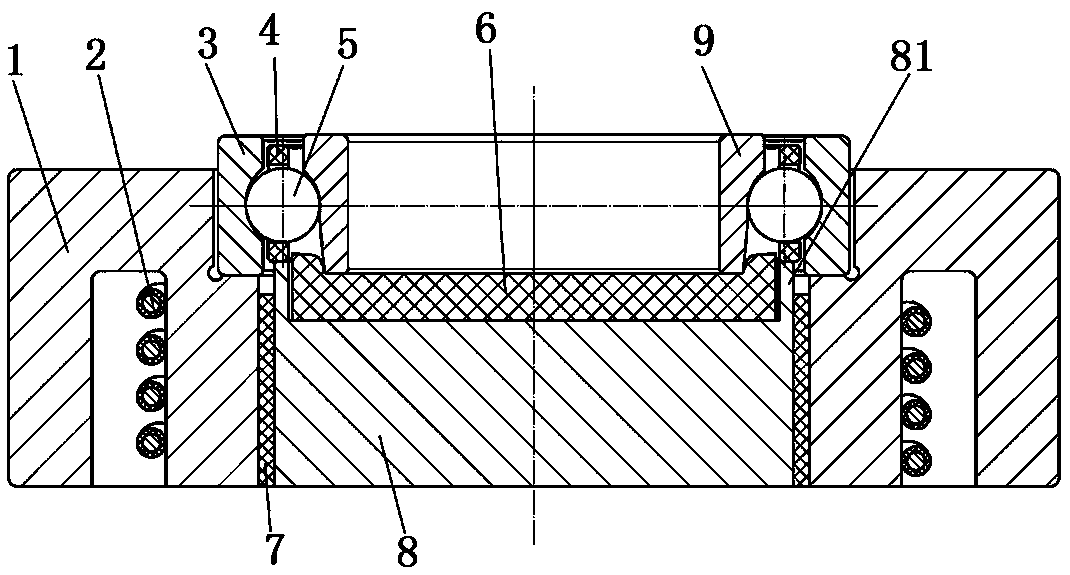
The invention relates to an angular contact ball bearing assembly fixture. When angular contact ball bearing assembling is carried out, a heated bearing outer ring is placed on an outer ring supporting step of a base assembly, a holder is placed on a holder supporting part of the base assembly, then a steel ball is placed on a supporting part of an elastic supporting piece, the steel ball is keptin a pocket, a bearing inner ring is finally installed in an inner hole defined by a holder ball in a pressing manner, the elastic supporting piece is compressed and deformed in the inner ring pressing fit process, and interference in the inner ring pressing fit process is avoided. In the using process of the assembly fixture, the supporting part of the elastic supporting piece is kept in the pocket of the holder, a lubrication agent is not needed for pasting the steel ball and the holder together, and lubrication agent washing after assembly in place is not needed; and when the fixture is used for assembling, operation is simple and convenient, and the problem that when an existing fixture is used for assembling, a lubrication agent is needed, and consequently the assembly efficiency is low is solved.
Description
technical field [0001] The invention relates to an angular contact ball bearing assembly tool. Background technique [0002] When assembling the angular contact ball bearing with the inner ring of the lock, the outer ring is usually heated first to expand the outer ring, and then the outer ring is removed, and the rolling elements are quickly bonded to the cage pocket and the cage pocket with Vaseline or other viscous medium. The space between the channels of the outer ring, and then the inner ring is pressed in to complete the assembly. In the assembly process of angular contact ball bearings, special tooling is required to ensure assembly accuracy and reduce assembly difficulty. For example, the Chinese patent with the authorized notification number CN 205978134 U discloses an angular contact ball bearing assembly tool, which includes a base and a mandrel installed in the inner hole of the base. During the assembly process of the bearing, the heated bearing Put the outer...
Claims
Login to View More Application Information
Patent Timeline
 IPC IPC(8): F16C43/04F16C43/06
CPCF16C43/04F16C43/065F16C2226/12F16C2226/14
Inventor 刘胜超张振强杨浩亮
Owner LUOYANG BEARING RES INST CO LTD
Features
- Generate Ideas
- Intellectual Property
- Life Sciences
- Materials
- Tech Scout
- Unparalleled Data Quality
- Higher Quality Content
- 60% Fewer Hallucinations
Learn More Browse by: Latest US Patents, China's latest patents, Technical Efficacy Thesaurus, Application Domain, Technology Topic, Popular Technical Reports.
© 2025 PatSnap. All rights reserved.Legal|Privacy policy|Modern Slavery Act Transparency Statement|Sitemap|About US| Contact US: help@patsnap.com