Oil tanks with level gauge for turbines

A turbine and box technology, applied in the direction of the engine level, turbine/propulsion device lubrication, measurement devices, etc., can solve complex quality and seal inspection problems, achieve the effects of optimizing accessibility, reducing costs, and improving measurement accuracy

Active Publication Date: 2021-06-08
SAFRAN AERO BOOSTERS SA
View PDF8 Cites 0 Cited by
  • Summary
  • Abstract
  • Description
  • Claims
  • Application Information

AI Technical Summary

Problems solved by technology

In addition, complex quality and sealing checks are required

Method used


Image

  • Oil tanks with level gauge for turbines
  • Oil tanks with level gauge for turbines
  • Oil tanks with level gauge for turbines

Examples


Embodiment Construction

[0056] In the following description, the axial direction corresponds to the direction in which the axis of rotation along the turbine is extended. The radial direction is perpendicular to the axis of rotation. The upstream and downstream refers to the main flow direction of the fluid in the turbine. The height and vertical aspect of the cabinet are related to the normal assembly direction.

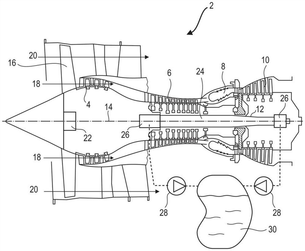
[0057] figure 1 It is a simplified schematic of a shaft turbine. In this specific case, it is a diblant scroll engine. The vortex engine 2 has a first compression stage called the low pressure compressor 4, referred to as a second compression stage, combustion chamber 8, and one or more turbine level 10 of the high pressure compressor 6. In operation, the mechanical power of the turbine 10 of the rotor 12 is transferred via the shaft to move the two compressors 4 and 6. The latter two have a plurality of roller blades associated with the arranged stator blade. Thereby, the rotor rotates about...


PUM

PropertyMeasurementUnit
thicknessaaaaaaaaaa
thicknessaaaaaaaaaa
thicknessaaaaaaaaaa

Abstract

The invention relates to an oil tank (30) fitted to a turbomachine, especially an aircraft turbojet engine. The tank (30) includes an inner cavity (36) containing oil of the turbine, a wall (42) having an inner surface (40) surrounding the inner cavity (36), and capacitive means for measuring the oil level. The device comprises at least one electrode (38) forming an inner surface (40), and possibly two parallel electrodes (38). These electrodes (38) are immersed in the oil to measure the oil level by measuring capacitance. The invention also proposes a method for manufacturing the tank (3), wherein the electrodes (30) are printed on the walls (42).

Description

Technical field [0001] The present invention relates to the level of measuring the liquid in the casing of the turbine. The present invention also proposes a shaft turbine including a box, especially aircraft vortex engine or aircraft. The present invention also proposes a method for manufacturing a box. Background technique [0002] The vortex engine is operated in operation. This fluid is used to lubricate, but it is also used for heat exchange. Heat exchange means cooling certain components and heating a plurality of regions that are subjected to frozen. Further, the oil can be pressurized to actuate the hydraulic cylinder. [0003] The fluid is a key role, and thus must be properly stored, and the amount of oil available in the vortex engine must be accurately measured. In order to meet the subsequent request, the oil box typically has a window for displaying the liquid level of the stored liquid. The window is a transparent glass component such that inside the cabinet can be...

Claims


Application Information

Patent Timeline
Patent Type & Authority Patents(China)
IPC IPC(8): F01M11/12B22F3/00B33Y10/00B22F10/10
CPCB33Y10/00B22F3/00F01M11/12F01D21/003F01D25/18F05D2260/98F16N19/003F16N2250/18Y02T50/60B33Y80/00B29C64/106B29K2995/0005B29L2031/712F02C7/06F05D2220/323F05D2230/30G01F23/263
Inventor N.赖马克斯F.瓦利诺G.乔达诺
Owner SAFRAN AERO BOOSTERS SA
Why Eureka
Try Eureka