Pressure-stabilizing milling shaper

A shaper and milling technology, which is applied to drilling equipment, wellbore/well parts, earthwork drilling and production, etc., can solve the problems of difficult pressurization and large friction resistance in horizontal wells, and achieve the solution of difficult pressurization and elimination of wear resistance big effect

Inactive Publication Date: 2018-02-23
PETROCHINA CO LTD +1
View PDF6 Cites 2 Cited by
  • Summary
  • Abstract
  • Description
  • Claims
  • Application Information

AI Technical Summary

Problems solved by technology

[0003] In order to overcome the shortage that the existing milling tools mainly rely on the weight of the pipe string to provide drilling pressure and have a large wear resistance in the horizontal section, the present invention provides a stabilized pressure milling shaper. The drill head provides drilling pressure, which eliminates the influence of high pipe string friction in the horizontal section and inclined well section, and solves the problem of difficult pressurization in horizontal wells

Method used


Image

  • Pressure-stabilizing milling shaper

Examples


Embodiment Construction

[0009] The present invention will be further described below in conjunction with accompanying drawing:

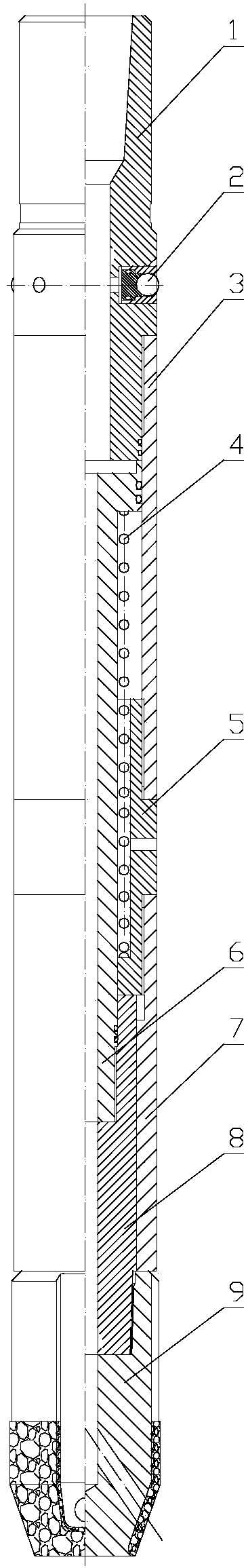
[0010] Depend on figure 1 As shown, a pressure-stabilizing milling and shaping device includes an upper joint 1 and a milling head 9. The upper part of the upper joint 1 is connected to a drilling tool, and the joint is coated with sealing grease to increase the sealing and pressure bearing capacity of the pipe string. A piston cylinder 3 is threadedly connected to the outer side of the lower part of the upper joint 1, and a piston 6 is arranged inside the piston cylinder 3, and a sealing ring is arranged between the piston cylinder 3 and the piston 6. The lower part of the piston cylinder 3 is connected with a joint 5, and the joint 5 is located outside the piston 6. A boss is provided outside the piston 6, and a spring 4 is arranged between the bottom of the boss and the joint 5, and the upper part of the spring 4 rests on the boss of the piston. , the lower part is stuc...


PUM


Abstract

The invention relates to a pressure-stabilizing milling shaper, which mainly solves the problem of larger milling drag in the horizontal section by mainly using self gravity of a tubular column to provide drilling pressure in the existing milling tool. The pressure-stabilizing milling shaper is characterized in that the lower part of an upper joint (1) is connected with a piston cylinder (3); a piston (6) is arranged in the piston cylinder (3); the lower part of the piston cylinder (3) is connected with a joint (5); the joint (5) is positioned at the exterior of the piston (6); a boss is arranged at the exterior of the piston (6); a spring (4) is arranged between the bottom part of the boss and the joint (5); the bottom part of the joint (5) is connected with a spline sleeve (7) by threads; the interior of the spline sleeve (7) is connected with a spline body (8); the spline body (8) is connected with the piston (6) by threads; the bottom part of the spline body (8) is connected with amilling head (9). The pressure-stabilizing milling shaper has the advantages that the hydraulic pressure is used for providing drilling pressure for a milling head, the influence of larger milling drag of the tubular column in the horizontal section and inclined shaft section is eliminated, and the problem of difficulty in pressurizing of a horizontal well is solved.

Description

technical field [0001] The invention relates to the field of oil fields, in particular to a pressure-stabilizing milling shaper used in the workover of horizontal wells in the oil field. Background technique [0002] With the extension of production time and the increase of operation times, the situation of horizontal well workover is becoming more and more serious. The commonly used grinding and milling tools for horizontal wells are mainly milling cones or milling shoes evolved from vertical wells. When these tools are milled, the drilling pressure is mainly provided by the dead weight of the pipe string. However, due to the particularity of the wellbore structure of horizontal wells, in The friction resistance of the inclined well section and the horizontal section is large, so it is difficult to apply the WOB by the string's own weight. Contents of the invention [0003] In order to overcome the shortage that the existing milling tools mainly rely on the weight of the...

Claims


Application Information

Patent Timeline
IPC IPC(8): E21B29/00E21B17/10
Inventor 史健搏马圣凯刘国军兰乘宇岳太振王彪
Owner PETROCHINA CO LTD
Why Eureka
Try Eureka