
Method for achieving temperature control in elevator car and elevator system

A technology for elevator car and temperature control, which is applied to air conditioning systems, elevators in buildings, heating methods, etc., and can solve problems such as easy blockage, expensive air conditioners, and difficult heat sinks for air conditioners

Inactive Publication Date: 2018-02-23
GUANGDONG HUANYU ELECTRONICS TECH CO LTD
View PDF9 Cites 12 Cited by
  • Summary
  • Abstract
  • Description
  • Claims
  • Application Information

AI Technical Summary

Problems solved by technology

Ordinary fans and cross-flow fans cannot achieve the effect of controlling the temperature and humidity of the elevator car. In hot summer and cold winter, it will make it extremely uncomfortable to take the elevator
Installing a common air conditioner in the elevator car can solve the temperature problem of the elevator car, but because: 1) the installation and maintenance of the air conditioner is quite difficult due to the limitation of the space of the elevator car; It is difficult to block easily, making it difficult for the air conditioner to achieve the expected cooling and heating effect; 3) the air conditioner is expensive and consumes a lot of power; 4) the traditional air conditioner has a compressor, and the operation noise is relatively loud
Because the traditional air conditioner is installed on the elevator, it will generate a lot of water droplets on the ceiling of the car roof, which will affect the safety of the elevator and the use of passengers. In addition, the water generated by the traditional air conditioner also needs to be checked and processed continuously, so it is difficult to install ordinary air conditioners in elevators. It is difficult to solve the problem of elevator ride comfort if it is popularized

Method used


Image

  • Method for achieving temperature control in elevator car and elevator system
  • Method for achieving temperature control in elevator car and elevator system
  • Method for achieving temperature control in elevator car and elevator system

Examples


Embodiment Construction

[0038] The following will clearly and completely describe the technical solutions in the embodiments of the present invention with reference to the accompanying drawings in the embodiments of the present invention. Obviously, the described embodiments are only some, not all, embodiments of the present invention. Based on the embodiments of the present invention, all other embodiments obtained by persons of ordinary skill in the art without creative efforts fall within the protection scope of the present invention.

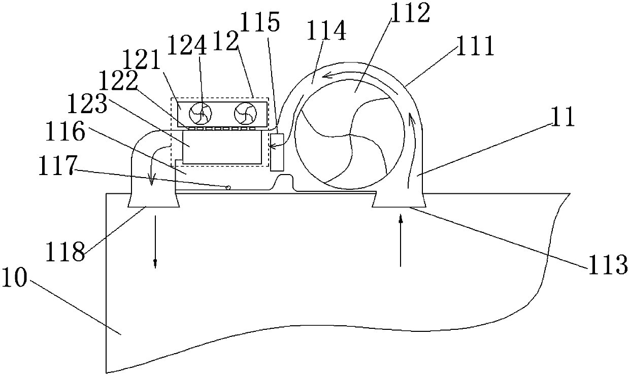
[0039]The semiconductor cooling and heating fan device applied to elevators according to the present invention can be fixed on the top of the elevator car or in the car, and includes a cross-flow fan and a semiconductor refrigerator. The cross-flow fan includes The casing and the cross-flow fan fixed in the casing are provided with an air inlet and an air outlet, and the air inlet and the air outlet are arranged on both sides of the cross-flow fan. The heat heater,...


PUM


Abstract

The invention discloses a method for achieving temperature control in an elevator car and an elevator system. The method comprises the steps that based on an elevator car controller, a user command isreceived and comprises a temperature control command; based on a temperature sensor, the current temperature in the elevator car is obtained; the magnitude and plus-minus relations between the current temperature and the temperature value in the temperature control command are judged, and based on the magnitude relation and the plus-minus relation, a semiconductor cooler work command and / or an air capacity control command are / or generated; the air capacity control command is sent to a motor driving a cross flow fan to work, so that the motor drives the cross flow fan to work; and the semiconductor cooler work command is sent to a semiconductor cooler, so that the semiconductor cooler works according to the semiconductor cooler work command. According to the method for achieving temperature control in the elevator car and the elevator system, the semiconductor refrigeration and heating effects can be controlled for the elevator car.

Description

technical field [0001] The invention relates to the technical field of elevators, in particular to a method for realizing temperature control in an elevator car and an elevator system. Background technique [0002] At present, the air supply system used in elevator cars generally adopts ordinary fans and cross-flow fans, and some elevators are equipped with ordinary air conditioners. Ordinary fans and cross-flow fans cannot achieve the effect of controlling the temperature and humidity of the elevator car. In hot summer and cold winter, it will make taking the elevator extremely uncomfortable. Installing a common air conditioner in the elevator car can solve the temperature problem of the elevator car, but because: 1) the installation and maintenance of the air conditioner is quite difficult due to the limitation of the space of the elevator car; It is difficult to block easily, making it difficult for the air conditioner to achieve the expected cooling and heating effect; ...

Claims


Application Information

Patent Timeline
IPC IPC(8): B66B11/02F24F5/00
CPCB66B11/024F24F5/0042
Inventor 黎梓燊郭智于马飞辉钟永浩
Owner GUANGDONG HUANYU ELECTRONICS TECH CO LTD
Learn More