
Device and method for beam forming for estimating direction of terminal

A beamforming, terminal technology, applied in measurement devices, radio wave measurement systems, receiver monitoring, etc., to achieve the effect of high received signal strength

Active Publication Date: 2018-02-16
SK TELECOM CO LTD
View PDF6 Cites 4 Cited by
  • Summary
  • Abstract
  • Description
  • Claims
  • Application Information

AI Technical Summary

Problems solved by technology

[0016] However, in the above method, it is necessary to utilize the data received from the entire beam used in each stage, and estimate the angle of the terminal (ie, the angle of arrival of the signal from the terminal) by performing matrix calculation on the data, which requires a relatively large amount of calculation

Method used


Image

  • Device and method for beam forming for estimating direction of terminal
  • Device and method for beam forming for estimating direction of terminal
  • Device and method for beam forming for estimating direction of terminal

Examples


Embodiment Construction

[0037] Hereinafter, operating principles of embodiments of the present invention will be described in detail with reference to the accompanying drawings. In the following description of the embodiments of the present invention, when a detailed description of known functions and configurations incorporated herein would make the subject matter of the present invention unclear, the detailed description will be omitted. In addition, the following terms are defined in consideration of functions used in the present invention, and may be changed according to user's intention or the like. Therefore, the limitation should be determined based on the contents of the specification.

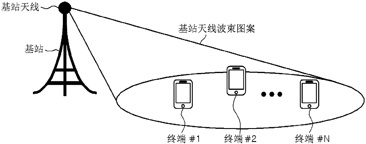
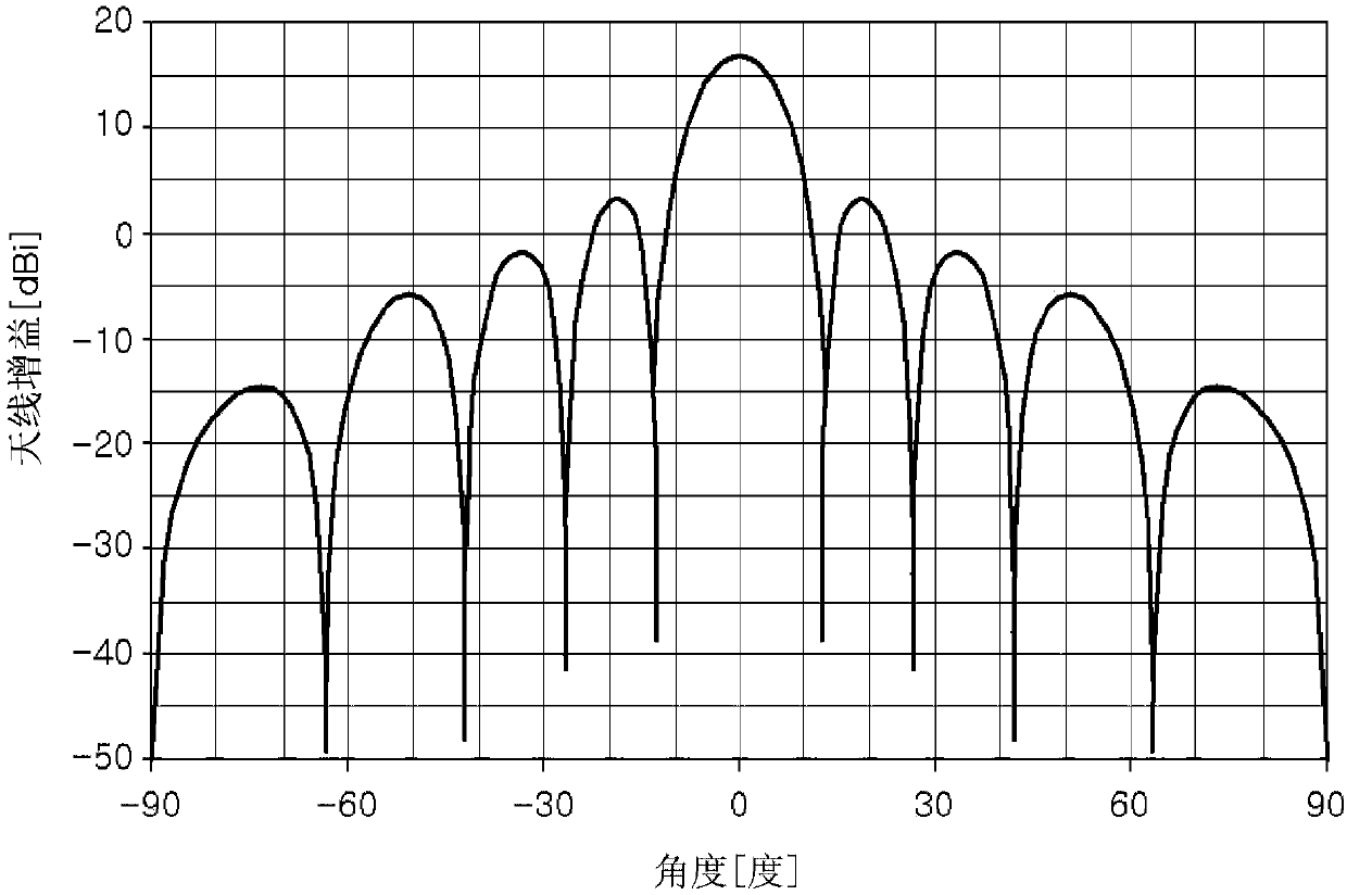
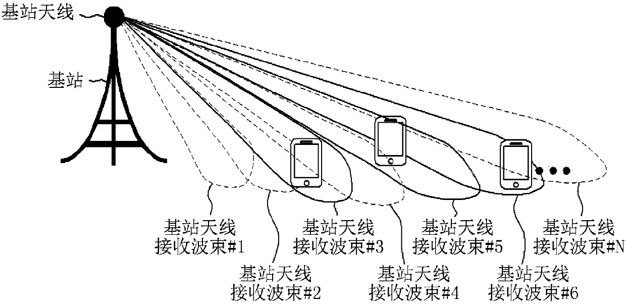
[0038] Figure 7 is a block diagram of a beamforming apparatus for estimating a direction of a terminal according to an embodiment of the present invention. The beamforming apparatus 700 includes a beam pattern measuring unit 702, a storage unit 704, a beamforming unit 706, a signal strength measuring unit ...


PUM


Abstract

A beam forming device is provided. The beam forming device comprises: a beam deriving unit for deriving, from among multiple reception beams, a first reception beam receiving, from a terminal, the largest reception signal and a second reception beam receiving, from the terminal, the second largest reception signal; and a control unit for estimating the direction of the terminal on the basis of a ratio value between the size of the reception signal received through the first reception beam and the size of the reception signal received through the second reception beam.

Description

technical field [0001] The present invention relates to a beamforming device and a beamforming method, and more particularly, to a beamforming device and a beamforming method in a higher frequency band-based wireless communication system using a plurality of antenna beams. Background technique [0002] The lower frequency band below 6 GHz, which is mainly used in current mobile communications, is completely used or divided by existing systems such as mobile communications, broadcasting, and satellite communications, making it difficult to secure ultra-wide bandwidth frequencies for large-capacity data transmission. [0003] As a result, centimeter waves such as 6 GHz or higher (electromagnetic waves having wavelengths in centimeters corresponding to the frequency range of 3 to 30 GHz) or millimeter waves (having wavelengths in millimeters corresponding to the frequency range of Electromagnetic waves) Such higher frequency bands become the key spectrum of the fifth generation...

Claims


Application Information

Patent Timeline
IPC IPC(8): H04B7/06G01S5/00H04B7/0413
CPCH04B7/04H04B7/06G01S5/0036H04B7/0617H04B7/088H04W64/006H04B17/27H04B17/318G01S5/10H04B7/0408H04B7/046H04B7/0885H04L5/0048
Inventor 朴海圣崔彰洵
Owner SK TELECOM CO LTD
Learn More