Device for changing a blade on shears, in particular for a rolled band, and shears with at least one replaceable blade

A technology for shearing machines and knives, which is applied in the direction of knives for shearing machine devices, devices for shearing forming blanks, shearing devices, etc., which can solve the troublesome cooling of knives and knives rollers, small loosening force, and time-consuming tool replacement Time and other problems, to achieve the effect of increasing the installation space and increasing the clamping force

Inactive Publication Date: 2018-02-16
SMS GRP GMBH
View PDF14 Cites 0 Cited by
  • Summary
  • Abstract
  • Description
  • Claims
  • Application Information

AI Technical Summary

Problems solved by technology

However, this fastening device has the disadvantage that due to the heat and media action during operation of the shear, the screw or bolt can easily become jammed after a certain operating time, so that the tool change is time-consuming
A disadvantage here is that the release force of the hydraulic cylinder installed in the cutter drum is limited due to the small structural dimensions, and for the same reason the clamping force of the spring element is also limited
In addition, the seals of the hydraulic cylinders are heat-sensitive, so that the tool and the tool drum must be cooled in a complex manner in order to limit the component temperature
Further disadvantages are the cumbersome production of the necessary bores in the cutter drum in order to feed the hydraulic oil to the hydraulic cylinders and the cumbersome provision of the connections for the hydraulic oil to the hydraulic cylinders at the outside of the shearing machine

Method used


Image

  • Device for changing a blade on shears, in particular for a rolled band, and shears with at least one replaceable blade
  • Device for changing a blade on shears, in particular for a rolled band, and shears with at least one replaceable blade
  • Device for changing a blade on shears, in particular for a rolled band, and shears with at least one replaceable blade

Examples


Embodiment Construction

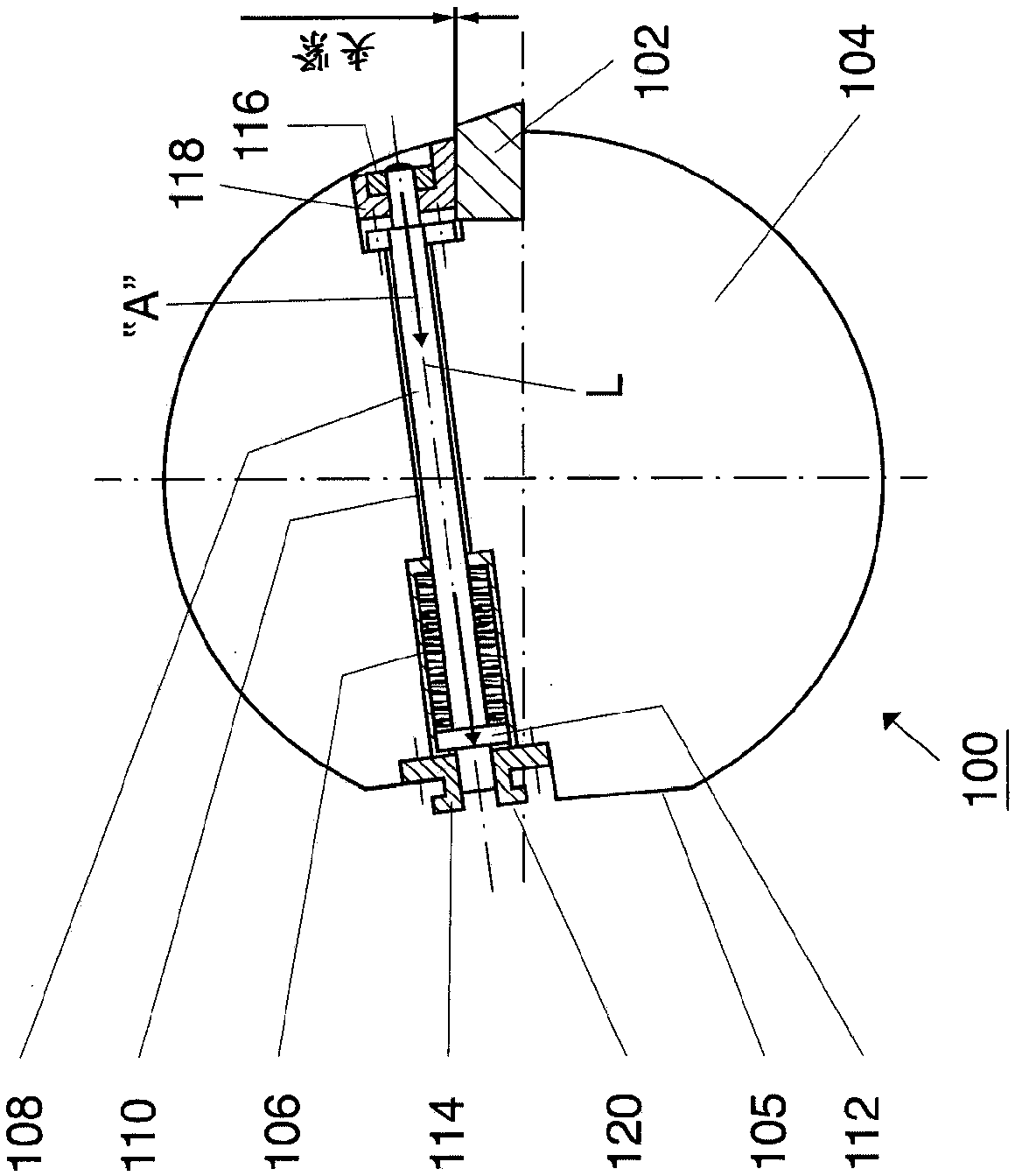
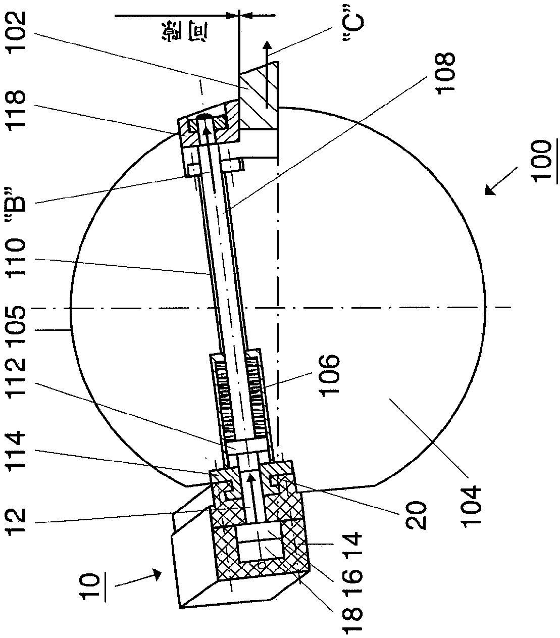
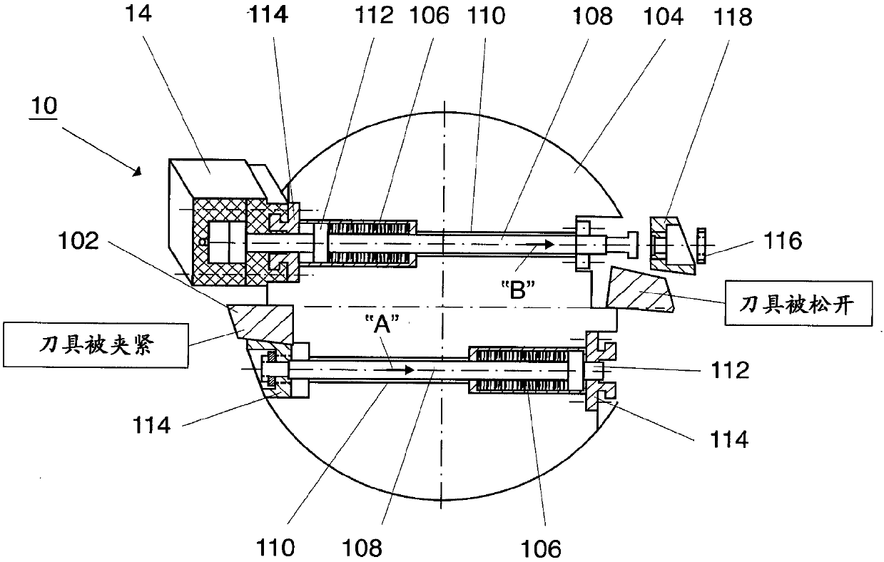
[0036] figure 1 A simplified side cross-sectional view of a shearing machine 100 according to the invention is shown, in which at least one knife 102 can be fixed by clamping on a knife holder 104 . The shearing machine 100 can be designed as a rotary shearing machine, wherein in this case the knife carrier 104 is a rotary knife drum. The tool 102 is clamped on the tool drum 104 by means of an energy accumulator 106 , via which a tie rod 108 acting on the tool 102 is pretensioned. The energy accumulator 106 is preferably constructed in the form of a coil spring and will hereinafter always be referred to simply as a coil spring, although in this regard it should not be understood as limiting the type of energy accumulator.

[0037] A borehole 110 is formed in the tool drum 104 in order to receive the coil spring 106 and the tie rod 108 therein. The coil spring 106 is mounted at the end of the tie rod 108 , wherein a base element 112 is fastened adjacent to the coil spring 106...


PUM


Abstract

The invention relates to a device (1) for changing a blade (102) on shears (100), in particular for a rolled band, and to such shears (100) in which a blade (102) can be fixed to at least one blade support (104) automatically ("A") by a tie bar (108) pretensioned by means of a force accumulator (106). The device (1) comprises at least one adjusting element (10) which can be actuated in order to release the blade (102) from the blade support (104) such that the tie rod (108) is moved in an axial direction ("B") against the tie rod pretension. The adjusting element (10) can be arranged on an outer face (105) of the blade support (104) or outside of the blade support (104).

Description

technical field [0001] The invention relates to a device according to the preamble of claim 1 and a device according to the preamble of claim 13 for changing a tool at a shearing machine, in particular for rolling strip This shearing machine. Background technique [0002] When shearing to sever or transversely separate the rolled strip, it is often necessary to replace the knives installed at the shears, since the knives are subject to severe wear during operation of the shears. Correspondingly, the fastening for mounting the knife on the shear can be released in order to properly replace the knife. [0003] Knife mounts in the form of screws or bolts are known in the prior art for shears of this type, which can be easily released in order to replace the knives. However, such fastening means have the disadvantage that, due to the heat and media effects during operation of the shear, the screw or bolt can easily become jammed after a certain operating time, so that the tool...

Claims


Application Information

Patent Timeline
Patent Type & Authority Applications(China)
IPC IPC(8): B23D25/12B23D35/00
CPCB23D25/12B23D35/002B23D35/008B23D35/00B26D7/26
Inventor T·伦克尔
Owner SMS GRP GMBH
Why Eureka
Try Eureka