End fitting mounting device for toothed belts and end fitting mounting method for toothed belts
An installation method and technology of toothed belts, applied in the direction of belt fasteners, transmission belts, belts/chains/gears, etc., can solve problems such as inability to work and no pressure device.
- Summary
- Abstract
- Description
- Claims
- Application Information
AI Technical Summary
Problems solved by technology
Method used
Image

Examples
no. 1 approach
[0064] -Construction of end-mounted devices for toothed belts-
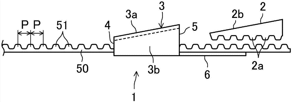
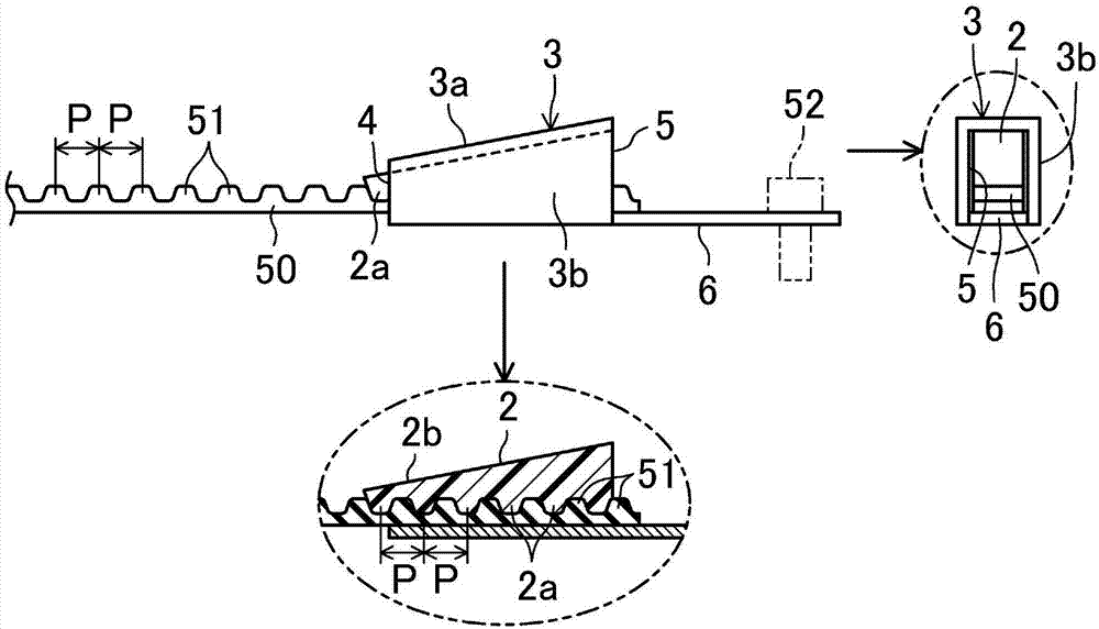
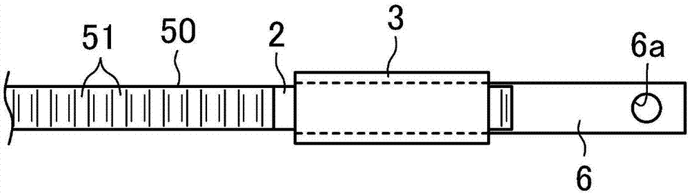
[0065] Figure 1 ~ Figure 3 The end attachment tool 1 of the toothed belt according to the first embodiment of the present invention is shown. In the present embodiment, the terminal mounting tool 1 is used to install a jointed toothed belt 50, and a plurality of tooth portions 51 are arranged on the surface of one side of the jointed toothed belt 50 at an equal pitch P (here, For simplicity, it is defined as the upper surface).
[0066] The terminal attachment tool 1 includes a wedge member 2 having a dummy tooth portion (dummy here means that the tooth portion does not operate) 2 a meshing with a tooth portion 51 of the toothed belt 50 . Such as figure 2 As shown, for example, five dummy tooth portions 2 a are arranged at an equal pitch P. Such as Figure 4 and Figure 5 As shown, the wedge member 2 has an inclined slope 2b, the wedge member 2 becomes thinner toward the tip, and is formed of, for example,...
no. 2 approach
[0086] Figure 8 A second embodiment of the present invention is shown. This second embodiment is different from the above-mentioned first embodiment in that a burring portion 107 is formed. It should be noted that, in the following embodiments, the same symbols are used to represent Figure 1 to Figure 7 The same part as in , the detailed description is omitted.
[0087] That is, if Figure 8 As shown, the flange portion 107 is integrally formed with the top end of the wedge member 102, and the flange portion 107 increases after passing through the belt insertion hole 4 to become a fall-off preventing portion. For example, the top end of the burring portion 107 is divided into two parts. When the wedge member 102 is inserted, the burring portion 107 is easily deformed due to the presence of the notch portion 107a at the left and right central positions. When the wedge member 102 is formed of a resin molded product, the burring portion 107 may be integrally molded with th...
no. 3 approach
[0095] Figure 11 The third embodiment of the present invention is shown, and the position of the burring portion 207 is different from that of the above-mentioned second embodiment.
[0096] That is to say, in this embodiment, the burring portion 207 is formed on the base end side (higher side) of the wedge member 202, and is cut along the left-right direction to form the notch portion 207a, and the base end of the wedge member 202 The side is easily deformed in the up and down direction.
[0097] The installation part 203 in this embodiment also has an inclined wall 203a. For example, the metal plate is bent and the side wall 203b is slightly opened to form the installation part 203 in this embodiment. The inner cylindrical part 203c formed by bending another metal plate can be inserted into this opening. In this embodiment, the inclined wall 203a, the belt insertion hole 4, and the wedge insertion hole 5 are divided by the inner cylinder portion 203c.
[0098] The burrin...
PUM
 Abstract
Description
Claims
Application Information
 - R&D
- Intellectual Property
- Life Sciences
- Materials
- Tech Scout
- Unparalleled Data Quality
- Higher Quality Content
- 60% Fewer Hallucinations
Browse by: Latest US Patents, China's latest patents, Technical Efficacy Thesaurus, Application Domain, Technology Topic, Popular Technical Reports.
© 2025 PatSnap. All rights reserved.Legal|Privacy policy|Modern Slavery Act Transparency Statement|Sitemap|About US| Contact US: help@patsnap.com