A brushless alternator and power generation technology
A technology of alternator and power generation unit, applied in electromechanical devices, electrical components, magnetic circuit shape/style/structure, etc., can solve the problems of limited speed, low reliability, complex structure, etc., and achieve high reliability and reliability Good performance and simplified rotor structure
- Summary
- Abstract
- Description
- Claims
- Application Information
AI Technical Summary
Problems solved by technology
Method used
Image

Examples
specific Embodiment approach 1
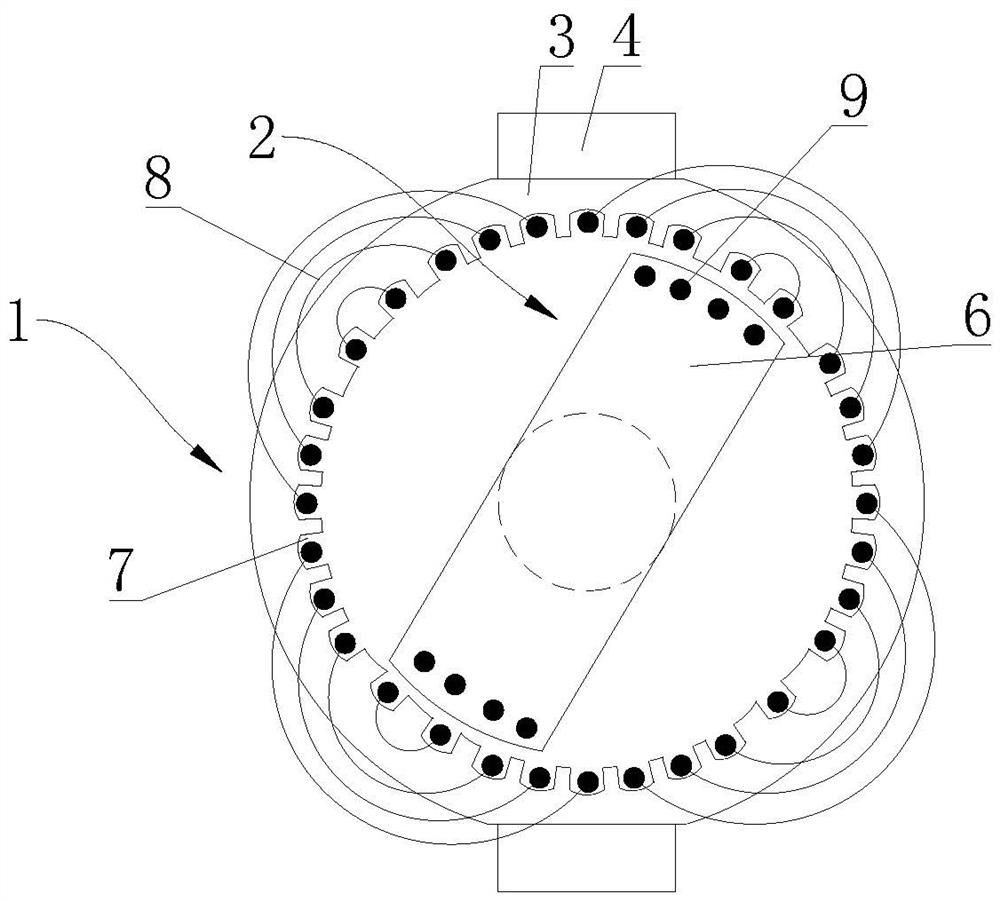
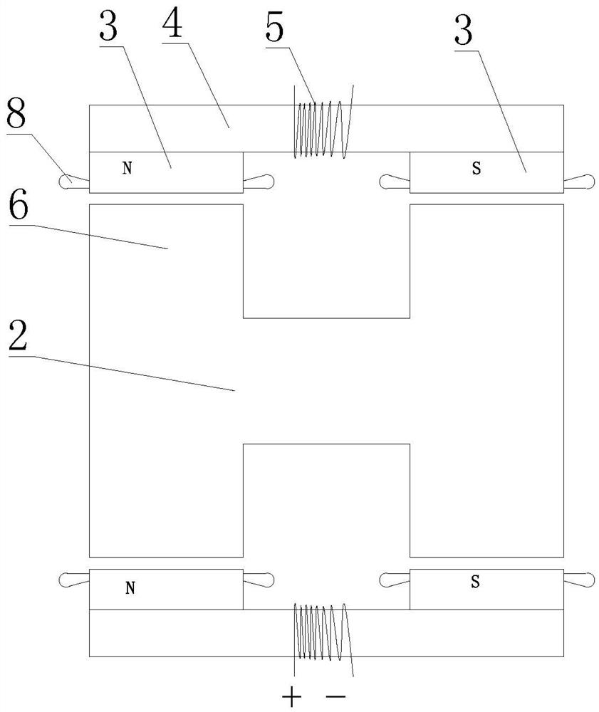
[0033] Specific implementation mode 1: see figure 1 , figure 2 , a brushless alternator in this embodiment includes a power generation unit, the power generation unit includes a stator 1 and a rotor 2, the rotor 2 is driven by a drive mechanism and can rotate relative to the stator 1, there is a gap between the stator 1 and the rotor 2 There is an air gap, the rotor 2 is arranged inside the stator 1, the stator includes a stator core 3 and an excitation support 4, two stator cores 3 and an excitation support 4 are respectively provided, and an excitation winding 5 is arranged on the excitation support 4, one of which is a stator core 3 They are respectively connected to one end of the two excitation supports 4, and the other stator core 3 is respectively connected to the other end of the two excitation supports 4, and the excitation support 4 forms a magnetic flux path so that the stator cores 3 at both ends of the excitation support 4 respectively form N pole and S pole, th...
specific Embodiment approach 2
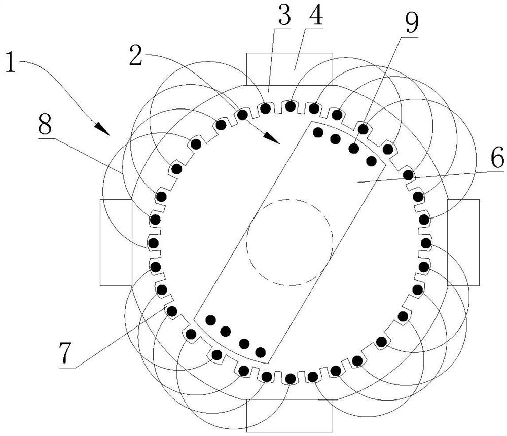
[0035] Specific implementation mode 2: see image 3 , Figure 4, a brushless alternator in this embodiment includes a power generation unit, the power generation unit includes a stator 1 and a rotor 2, the rotor 2 is driven by a drive mechanism and can rotate relative to the stator 1, there is a gap between the stator 1 and the rotor 2 There is an air gap, and the rotor 2 is set inside the stator 1. The stator includes a stator core 3 and an excitation support 4. There are two stator cores 3 and four excitation supports 4. One of the stator cores 3 is connected to the four excitation supports 4 respectively. The other end of the stator core 3 is connected to the other end of the four excitation brackets 4 respectively. The excitation winding 5 is arranged on the excitation bracket 4, and the excitation bracket 4 forms a magnetic flux path so that the stator core 3 at both ends of the excitation bracket 4 N poles and S poles are formed respectively. The two ends of the rotor 2...
specific Embodiment approach 3
[0036] Specific implementation mode 3: see Figure 5 , Figure 6 , a brushless alternator in this embodiment includes a power generation unit, the power generation unit includes a stator 1 and a rotor 2, the rotor 2 is driven by a drive mechanism and can rotate relative to the stator 1, there is a gap between the stator 1 and the rotor 2 There is an air gap, the rotor 2 is arranged inside the stator 1, the stator includes a stator core 3 and an excitation support 4, two stator cores 3 and an excitation support 4 are respectively provided, and an excitation winding 5 is arranged on the excitation support 4, one of which is a stator core 3 They are respectively connected to one end of the two excitation supports 4, and the other stator core 3 is respectively connected to the other end of the two excitation supports 4, and the excitation support 4 forms a magnetic flux path so that the stator cores 3 at both ends of the excitation support 4 respectively form N pole and S pole, t...
PUM
 Abstract
Description
Claims
Application Information
 - R&D
- Intellectual Property
- Life Sciences
- Materials
- Tech Scout
- Unparalleled Data Quality
- Higher Quality Content
- 60% Fewer Hallucinations
Browse by: Latest US Patents, China's latest patents, Technical Efficacy Thesaurus, Application Domain, Technology Topic, Popular Technical Reports.
© 2025 PatSnap. All rights reserved.Legal|Privacy policy|Modern Slavery Act Transparency Statement|Sitemap|About US| Contact US: help@patsnap.com