
A zoom mechanism for optical instruments

A technology of mechanical devices and optical instruments, applied in the field of zooming of large-scale optical instruments, can solve the problems of difficult processing, easy to be affected by temperature, complex structure, etc., and achieve the effect of stabilizing images

Active Publication Date: 2020-09-01
CHANGCHUN INST OF OPTICS FINE MECHANICS & PHYSICS CHINESE ACAD OF SCI
View PDF4 Cites 0 Cited by
  • Summary
  • Abstract
  • Description
  • Claims
  • Application Information

AI Technical Summary

Problems solved by technology

The traditional zoom device has a complex structure, difficult processing, difficult assembly and adjustment, and it is difficult to eliminate processing errors, transmission errors and assembly errors. The mechanism is prone to backlash and gaps during the working process. The above factors may lead to unclear imaging of the optical system

Method used


Image

  • A zoom mechanism for optical instruments
  • A zoom mechanism for optical instruments

Examples


Embodiment Construction

[0025] Embodiments of the present invention are described in detail below, examples of which are shown in the drawings, wherein the same or similar reference numerals designate the same or similar elements or elements having the same or similar functions throughout. The embodiments described below by referring to the figures are exemplary and are intended to explain the present invention and should not be construed as limiting the present invention.

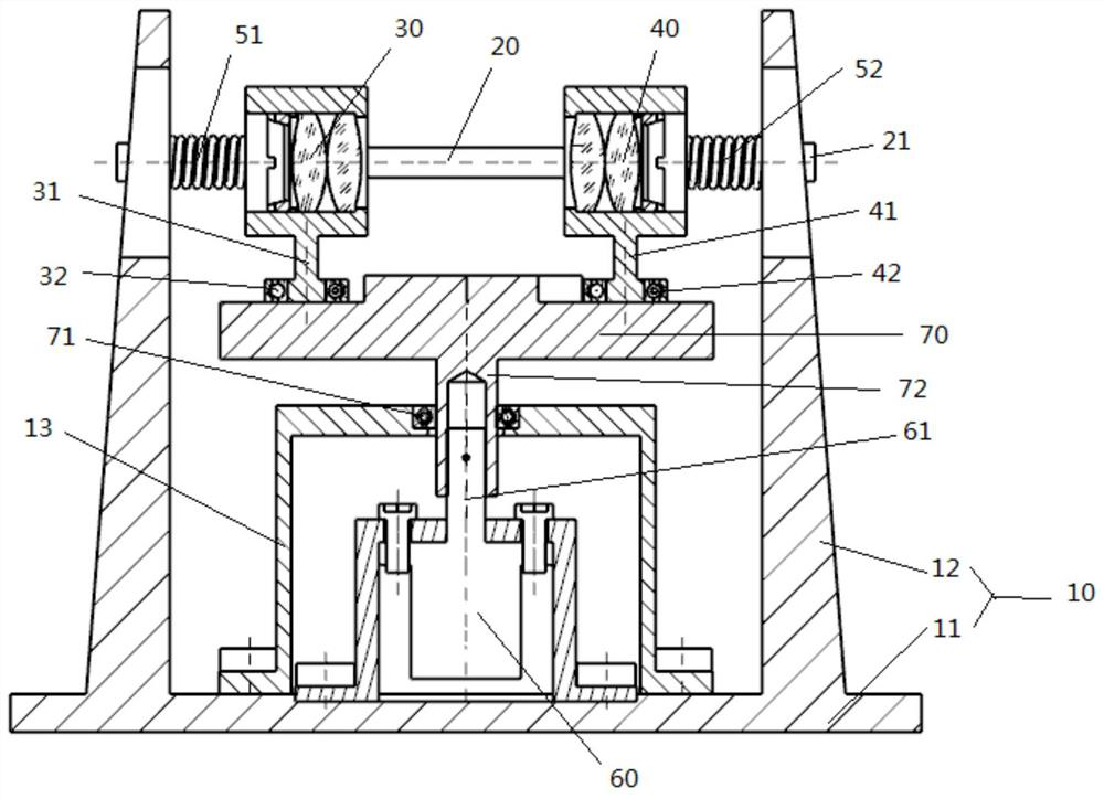
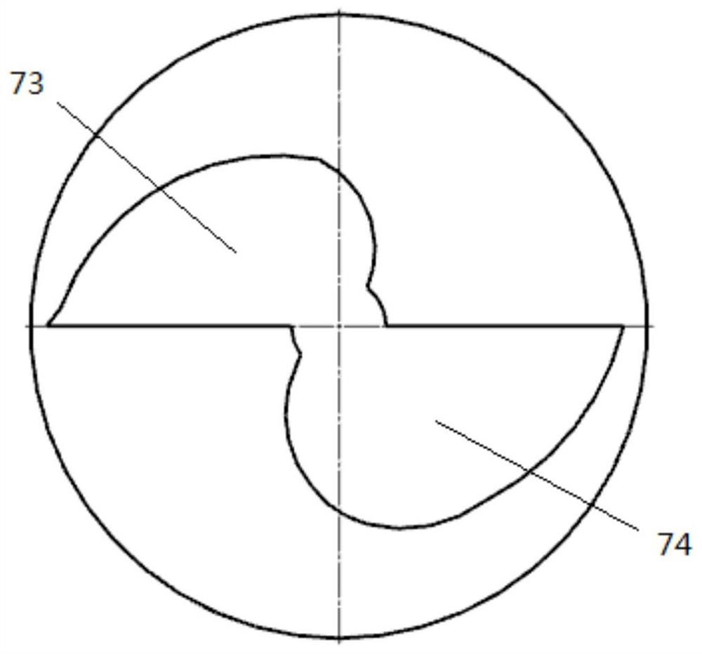
[0026] The following will be combined with figure 1 And attached figure 2 DETAILED DESCRIPTION The present invention provides a zoom mechanism for optical instruments.

[0027] Such as figure 1 As shown, the zoom mechanism for optical instruments provided by the present invention includes a bracket 10, which is used to support the entire zoom mechanism for optical instruments, serving as an installation platform and a support platform for the entire device.

[0028] The guide rail 20 is arranged on the support 10 . The guide...


PUM


Abstract

The invention provides a zoom mechanism for optical instruments, which is characterized in that it includes a bracket, a guide rail, a zoom lens group, a compensation lens group, a first return spring, a second return spring, a motor and a planar cam. The magnification lens group is set in cooperation with the plane cam, and the rotation of the plane cam can drive the zoom lens group to slide on the guide rail in a direction away from the compensation lens group; the compensation lens group and the plane The cams are arranged in cooperation, and the rotation of the plane cam can drive the compensation lens group to slide on the guide rail in a direction away from the zoom lens group. The zooming mechanical device for optical instruments provided by the invention can continuously and stably change the focal length data, precisely adjust the focus, and obtain clear and stable images.

Description

technical field [0001] The invention relates to the zooming field of large optical instruments, in particular to a zooming mechanical device for optical instruments. Background technique [0002] In the optical system in the field of large optical instruments, the zoom system is a commonly used optical system design; especially for tracking and measuring dynamic targets, such as rockets, missiles, aircraft, etc., the design of the zoom system is particularly important. [0003] The traditional zoom device is driven by a motor through a gear to rotate a cylindrical cam, and through the zoom curve on the cam, the compensation curve drives the zoom lens group, and the compensation lens group generates relative motion in the optical path to achieve the purpose of changing the focal length. The traditional zoom device has a complex structure, difficult processing, difficult assembly and adjustment, and it is difficult to eliminate processing errors, transmission errors and assemb...

Claims


Application Information

Patent Timeline
Patent Type & Authority Patents(China)
IPC IPC(8): G02B7/04G02B7/08G02B27/64
CPCG02B7/04G02B7/08G02B27/646
Inventor 李红光
Owner CHANGCHUN INST OF OPTICS FINE MECHANICS & PHYSICS CHINESE ACAD OF SCI
Learn More