
Spray room roller bed

A technology of roller bed and spray booth, which is applied in the direction of roller table, conveyor, transportation and packaging, etc. It can solve the problems of complex structure of tensioning components, high motor requirements, poor transmission effect, etc., and achieve better tensioning effect, The effect of scraping paint thoroughly and taking up little space

Pending Publication Date: 2018-02-16
MIRACLE AUTOMATION ENG CO LTD
View PDF9 Cites 0 Cited by
  • Summary
  • Abstract
  • Description
  • Claims
  • Application Information

AI Technical Summary

Problems solved by technology

[0002] In the process of automobile processing, it needs to be painted. In the prior art, a chain is used to drive the rollers of the roller bed in the spray booth, and the transmission effect is poor; the structure of the tensioning component is complex and takes up a lot of space; the drive is built-in. Higher requirements on the motor

Method used


Image

  • Spray room roller bed
  • Spray room roller bed
  • Spray room roller bed

Examples


Embodiment Construction

[0030] The present invention will be further described below in combination with specific embodiments and accompanying drawings.

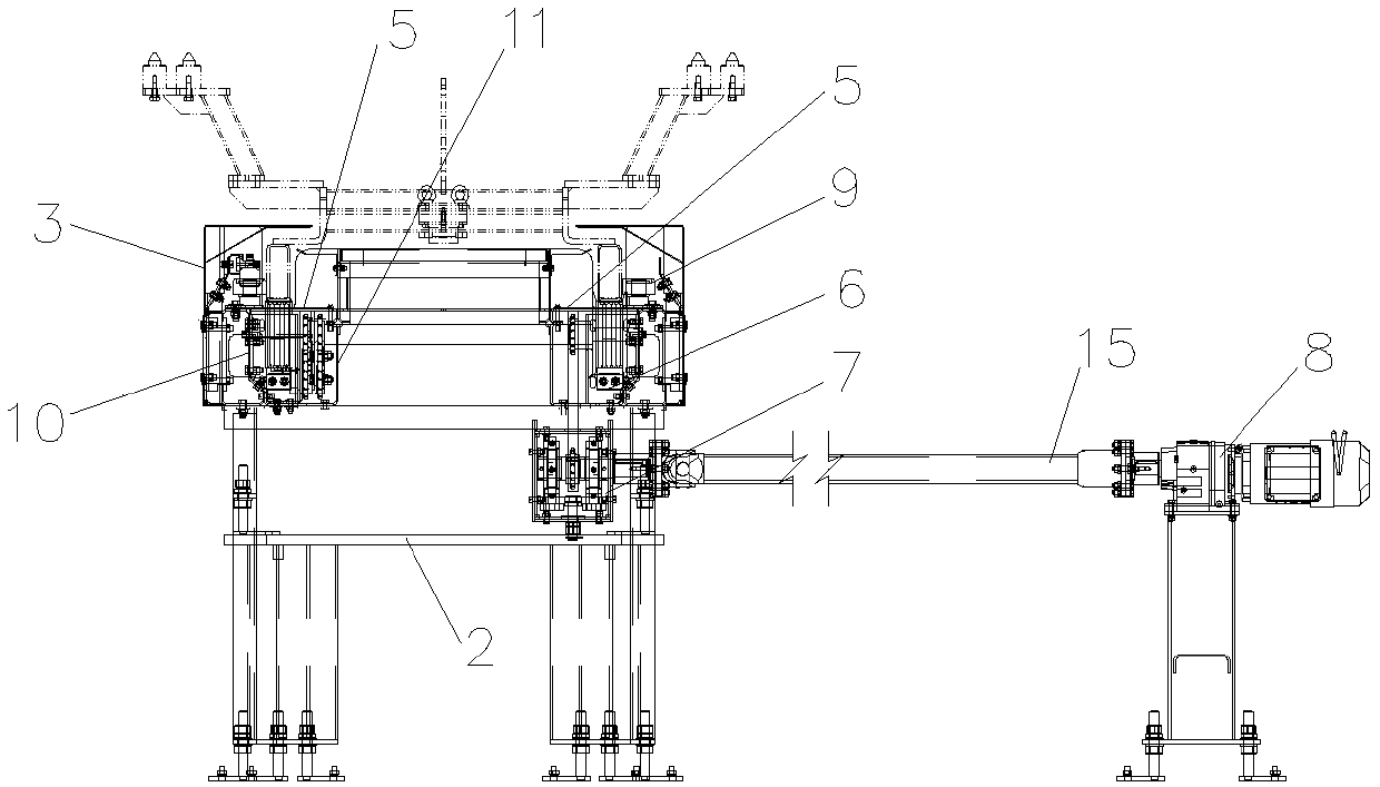
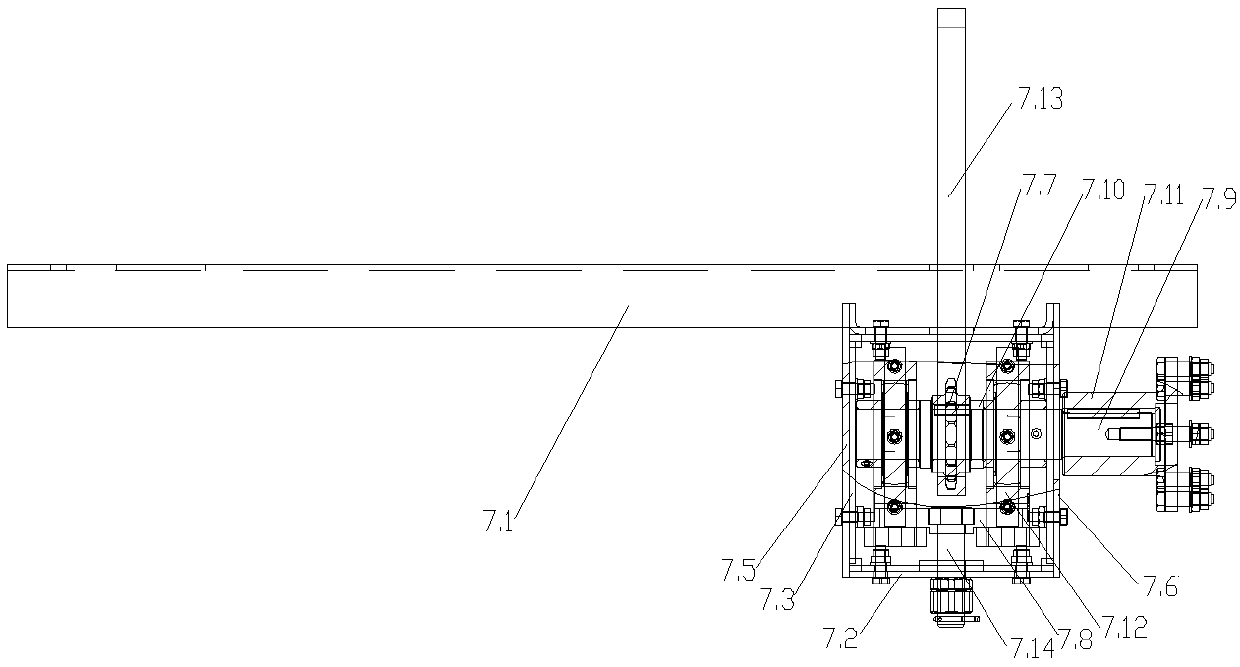
[0031] Such as Figure 1-3 Shown: spray booth roller bed, including outer cover plate assembly 3, roller 13 and drive assembly 8, a plurality of rollers 13 are arranged in parallel in the outer cover plate assembly 3, and an independent chain 14 is respectively arranged between two adjacent rollers 13 , each chain 14 is respectively connected with sprockets installed on two adjacent rollers 13, and each chain 14 is provided with a tensioning assembly 4. A paint scraper assembly 6 is provided under the pulleys at both ends of the roller 13 . The drive assembly 8 is connected to one of the rollers 13 by means of the drive tension assembly 7 .

[0032] Side plates 10 are installed in the side walls of the outer cover plate assembly 3 , and the two ends of the rollers 13 are installed on the side plates 10 on both sides. The upper end of the side pl...


PUM


Abstract

The invention discloses a spray room roller bed. The spray room roller bed comprises an outer cover plate assembly, rollers and a driving assembly. The multiple rollers are parallelly arranged in theouter cover plate assembly, an independent chain is arranged between every two adjacent rollers, and each chain is connected with chain wheels installed on the corresponding two adjacent rollers and is provided with a tensioning assembly; a paint scraping plate assembly is arranged under belt wheels at the two ends of each roller; and the driving assembly is in transmission connection with one ofthe rollers through a driving tensioning assembly. The spray room roller bed has the advantages that the transmission effect is good; the outer cover plate assembly is convenient to disassemble; the tensioning assemblies are simple in structure and small in occupied space; the driving assembly can be arranged outside, and the requirements for a motor are lowered; and the paint scraping plate assemblies adopt toothed paint scraping plates to scrape paint, so that paint scraping is more thorough.

Description

technical field [0001] The invention relates to a spray booth roller bed. Background technique [0002] In the process of automobile processing, it needs to be painted. In the prior art, a chain is used to drive the rollers of the roller bed in the spray booth, and the transmission effect is poor; the structure of the tensioning component is complex and takes up a lot of space; the drive is built-in. Higher requirements are placed on the motor. Contents of the invention [0003] The purpose of the present invention is to solve the problems existing in the prior art, and provide a spray booth roller bed, which can improve the transmission effect and reduce the requirement on the motor. [0004] According to the technical solution of the present invention, the spray booth roller bed includes an outer cover plate assembly, rollers and a driving assembly, a plurality of rollers are arranged in parallel in the outer cover plate assembly, and an independent chain is respectivel...

Claims


Application Information

Patent Timeline
Patent Type & Authority Applications(China)
IPC IPC(8): B65G13/07B65G23/44
CPCB65G13/07B65G23/44
Inventor 黄正君强秋霞吕翔宇
Owner MIRACLE AUTOMATION ENG CO LTD
Learn More