cosmetic liquid storage bottle

A technology of cosmetic liquid and liquid discharge port, which is applied in the field of daily necessities, can solve the problems of inconvenient carrying, large space occupation, and easy collision, etc., and achieve the effect of convenient portability and small space occupation

Active Publication Date: 2019-03-22
刘芮琪
View PDF9 Cites 0 Cited by
  • Summary
  • Abstract
  • Description
  • Claims
  • Application Information

AI Technical Summary

Problems solved by technology

[0003] The purpose of the present invention is to propose a cosmetic liquid storage bottle, which solves the problems of large space occupation, inconvenient carrying and easy collision in the prior art

Method used


Image

  • cosmetic liquid storage bottle
  • cosmetic liquid storage bottle
  • cosmetic liquid storage bottle

Examples


Embodiment 1

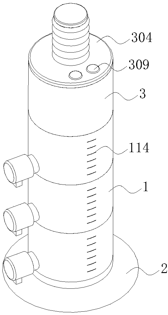
[0042] See attached figure 1 - attached Figure 7 , a cosmetic liquid storage bottle of the present invention comprises:

[0043] A plurality of detachably connected containing boxes 1 arranged up and down in sequence, each containing box 1 includes a box body 101, a piston 102 slidingly fitted with the inner wall of the box body 101, and a guide rod 104 vertically fixed on the upper end of the piston 102; the piston 102 The box body 101 is divided into an upper pressure relief chamber 105 and a lower discharge chamber 106, a pressure relief hole 103 connecting the pressure relief chamber 105 and the discharge chamber 106 is opened on the piston 102, and a through hole is opened on the lower end surface of the box body 101 , the lower end of the side wall has a protruding structure, and the lower end of the protruding structure has a liquid discharge port 111, and the protruding structure is connected to a liquid discharge structure; the guide rods 104 located at the bottom o...

Embodiment 2

[0063] The difference between this embodiment and Embodiment 1 is:

[0064] The control unit 3 includes:

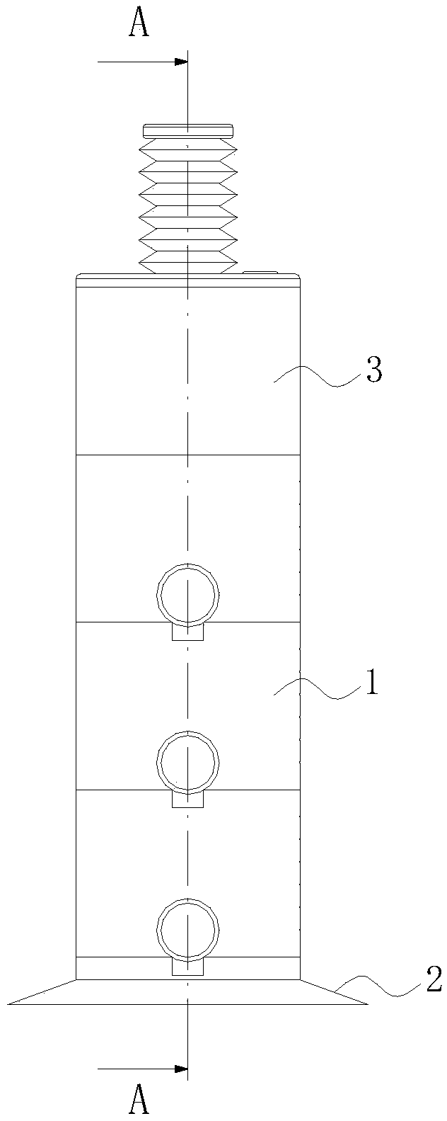
[0065] A control box 301 detachably connected to the uppermost box body 101 of a plurality of storage boxes 1, the lower end of the control box 301 has a through hole, and is matched with the uppermost guide rod 104;

[0066] The upper cover 304 that is arranged on the upper end of the control box 301;

[0067] The lower end passes through the upper cover 304 and the T-shaped pressing rod 302 that is in contact with the upper end of the guide rod 104 extending into the control box 301;

[0068] And a recovery structure arranged between the cross bar of the T-shaped pressing bar 302 and the upper end surface of the upper cover 304 .

[0069] The recovery structure includes a bellows 305 and a return spring 306 sleeved on the T-shaped pressing rod 302 .

[0070] The application process of the present invention is as follows: select a corresponding number of storage boxes...


PUM


Abstract

The invention discloses a cosmetic liquid storage bottle, and belongs to the technical field of daily necessities. The problems of large occupied space, inconvenient carrying and easy collision in theprior art are solved. The cosmetic liquid storage bottle comprises a plurality of detachably-connected holding boxes which are sequentially arranged up and down, a lower sealing body and a control unit, each holding box comprises a box body, a piston which is in sliding fit with the inner wall of each box body and a guide rod vertically fixed at the upper end of the piston; each piston divides the corresponding box body into an upper pressure relief cavity on the upper portion and a discharge cavity on the lower portion, and a pressure relief hole communicating with the pressure relief cavityand the discharge cavity are formed in each piston; a through hole is formed in the lower end face of each box body, the lower end of the side wall is provided with an extending-out structure, a liquid discharging port is formed in the lower end of the extending-out structure, and the extending-out structure and one liquid discharging structure are connected; and the guide rod located at the lower portion of the two adjacent holding boxes penetrates through the through hole of the lower end of the box body located on the upper portion and makes contact with the corresponding piston; and the lower sealing body is located at the lower ends of the multiple holding boxes, and the control unit is arranged at the upper ends of the multiple holding boxes and controls the guide rod to move up anddown.

Description

technical field [0001] The invention belongs to the technical field of daily necessities, and in particular relates to a cosmetic liquid storage bottle. Background technique [0002] Makeup is an essential daily routine for girls, and there are a wide variety of cosmetics and toiletries with different functions and types. Because there are many types of cosmetics, and they are all separately packaged independently, women need to carry multiple packaging containers, which is very inconvenient. Moreover, since cosmetics cannot be in contact with the external environment for a long time, cosmetic containers are mostly made of glass, which is not only heavy, but also prone to collisions in bags when carried, and makes noise when walking. Moreover, when women need to go out on business trips or travel, the cosmetic packaging of these bottles and cans needs to be carried in a larger space, causing inconvenience to travel. So be badly in need of a kind of utensil that can be conv...

Claims


Application Information

Patent Timeline
Patent Type & Authority Patents(China)
IPC IPC(8): B65D47/34
CPCB05B11/0078B05B11/025
Inventor 刘芮琪
Owner 刘芮琪
Why Eureka
Try Eureka