
Integral movable cutting device with adjustable interval between cutting wires

A cutting device and cutting wire technology, applied in metal processing and other directions, can solve the problems of difficult and dangerous operation, high cost, low production efficiency, etc., and achieve the effects of avoiding artificial positioning errors, realizing precise control, and improving production efficiency.

Pending Publication Date: 2018-02-16
许昌五星实业有限责任公司
View PDF8 Cites 4 Cited by
  • Summary
  • Abstract
  • Description
  • Claims
  • Application Information

AI Technical Summary

Problems solved by technology

[0002] At present, the production line of self-insulating blocks adopts wet and dry cutting. Dry cutting often uses electric saws to repeatedly cut the blocks after the self-insulating blocks are formed and dried. On the one hand, the wallboards cut by this method are uneven in thickness, Difficult operation has a certain degree of danger, and it is easy to cause injury to the operator. On the other hand, due to the dry cutting method, a large amount of dust will be generated, which not only pollutes the working environment of the staff, but also is in line with the goal of the company to build a green and environmentally friendly factory. to violate
Most of the existing self-insulating blocks are cut by wet method, that is, they are cut after forming and before drying. However, the structure of the existing wet-cut self-insulating block cutting equipment is not reasonable enough, the floor area is large, and the degree of automation is low. , the staffing in the production process is also relatively large, the cost of the entire process is high, and the production efficiency is low, resulting in high production costs

Method used


Image

  • Integral movable cutting device with adjustable interval between cutting wires
  • Integral movable cutting device with adjustable interval between cutting wires
  • Integral movable cutting device with adjustable interval between cutting wires

Examples


Embodiment Construction

[0030] In order to make the technical solutions and advantages of the present invention clearer, the present invention will be further described in detail below in conjunction with the accompanying drawings and embodiments.

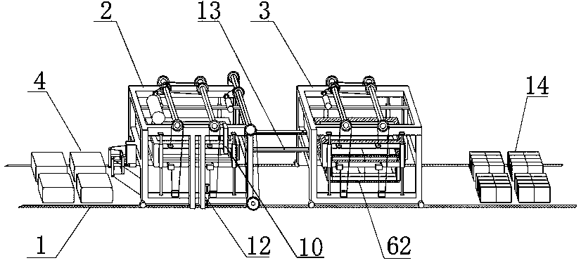
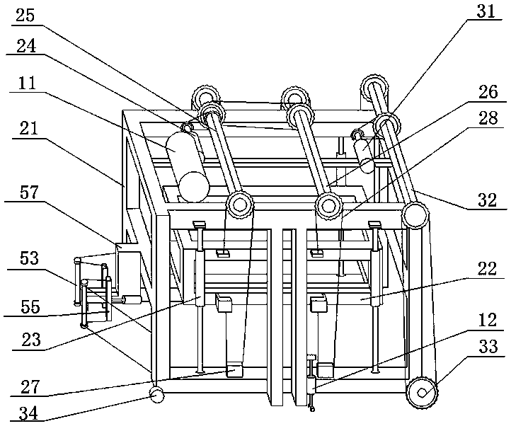
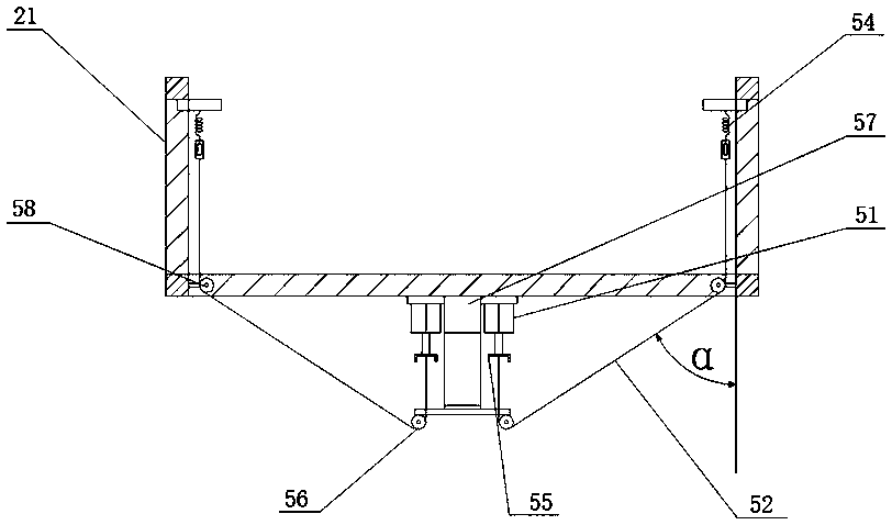
[0031] As shown in the figure: the embodiment of the present invention provides a one-piece mobile cutting device with adjustable cutting wire spacing, which includes two parallel slide rails 1 for cutting the upper and lower end faces 5 and side faces of the self-insulating block body 4 . Cutting machine one 2 for cutting the end face 6 along the direction parallel to the side end face 6, cutting machine two 3 for cutting the front and rear end faces 7 of the self-insulating block body 4 and cutting along the parallel direction of the front and rear end faces 7, and connecting rod 13 , The connecting rods 13 are two and arranged in parallel, and the two ends of each connecting rod 13 are respectively connected to the cutting machine 1 2 and the cutting ma...


PUM


Abstract

The invention provides an integral movable cutting device with the adjustable interval between cutting wires. The integral movable cutting device comprises two sliding rails arranged in parallel, a first cutting machine, a second cutting machine and a connecting rod, wherein the first cutting machine is used for cutting upper and lower end faces and side end faces of self-heat-preserving buildingblock blanks and carries out slitting in the parallel direction of the side end faces, and the second cutting machine is used for cutting front and rear end faces of the self-heat-preserving buildingblock blanks and carries out slitting in the parallel direction of the third end face. The two ends of the connecting rod are fixedly connected with the first cutting machine and the second cutting machine correspondingly. According to the movable cutting device, a wetting method is adopted for cutting, one traveling mechanism can be shared, the production efficiency is improved greatly, the laborcost is reduced, the labor intensity is low, the interval between the cutting wires is adjustable, and practicability and operability of the production line are improved greatly. According to the movable cutting device, one-person operation can be achieved completely, moreover, no dust is generated in the production process, and the movable cutting device is consistent with the aim of enterprisesto build green environment-friendly factories.

Description

technical field [0001] The invention belongs to the technical field of production equipment for building self-insulating blocks, and in particular relates to a movable cutting device with adjustable spacing between cutting wires. Background technique [0002] At present, the production line of self-insulating blocks adopts wet and dry cutting. Dry cutting often uses electric saws to cut the blocks repeatedly after the self-insulating blocks are formed and dried. On the one hand, the wallboards cut by this method are uneven in thickness. Difficult operation has a certain degree of danger, and it is easy to cause injury to the operator. On the other hand, due to the dry cutting method, a large amount of dust will be generated, which not only pollutes the working environment of the staff, but also is in line with the goal of the company to build a green and environmentally friendly factory. violated. Most of the existing self-insulating blocks are cut by wet method, that is, t...

Claims


Application Information

Patent Timeline
IPC IPC(8): B28D1/14B26D7/26B26D1/553
CPCB26D1/553B26D7/2628B28D1/14Y02W30/82
Inventor 李孝武李信广李光耀臧继业田国成
Owner 许昌五星实业有限责任公司
Learn More