
Rechargeable gun protective structure of novel energy electric vehicle

A protective structure and electric vehicle technology, applied in electric vehicle charging technology, electric vehicles, charging stations, etc., can solve problems affecting aesthetics, affecting normal use, inconvenient operation, etc., and achieve the effect of sealing protection

Inactive Publication Date: 2018-02-13
黄国华
View PDF2 Cites 1 Cited by
  • Summary
  • Abstract
  • Description
  • Claims
  • Application Information

AI Technical Summary

Problems solved by technology

[0002] The new energy electric vehicle is charged through the charging pile, and the charging pile is inserted into the charging interface of the electric vehicle through the charging gun. The head of the charging gun is provided with more than one terminal and an assembly hole. The assembly hole is used for matching the charging interface, and the terminal is inserted into the charging port. The power transmission is completed in the jack, however, the charging gun terminal has the risk of water entering when not in use, and external objects will damage the terminal, so the traditional method is to set a protective cover outside the charging gun to protect each terminal through the protective cover , but after setting the protective cover, the entire protective cover is a separate body, which will swing when using the charging gun, which will affect the normal use. After use, it will be placed on the gun head, which is inconvenient to operate and affects the aesthetic

Method used


Image

  • Rechargeable gun protective structure of novel energy electric vehicle
  • Rechargeable gun protective structure of novel energy electric vehicle
  • Rechargeable gun protective structure of novel energy electric vehicle

Examples


Embodiment Construction

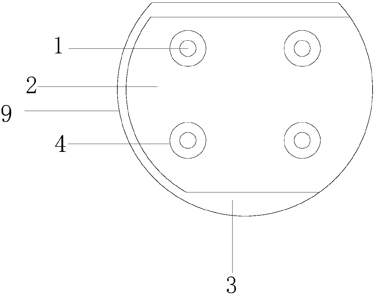
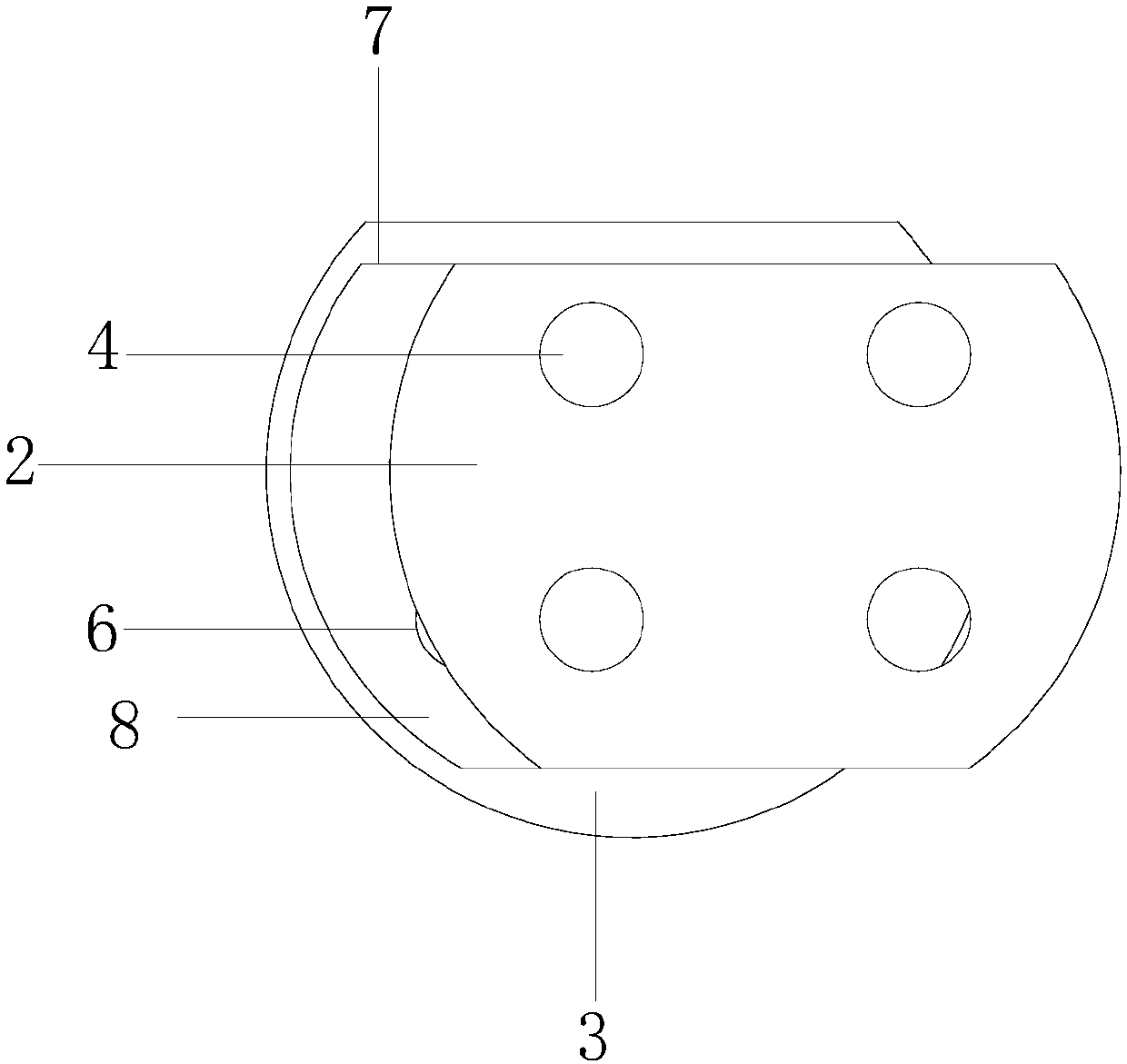
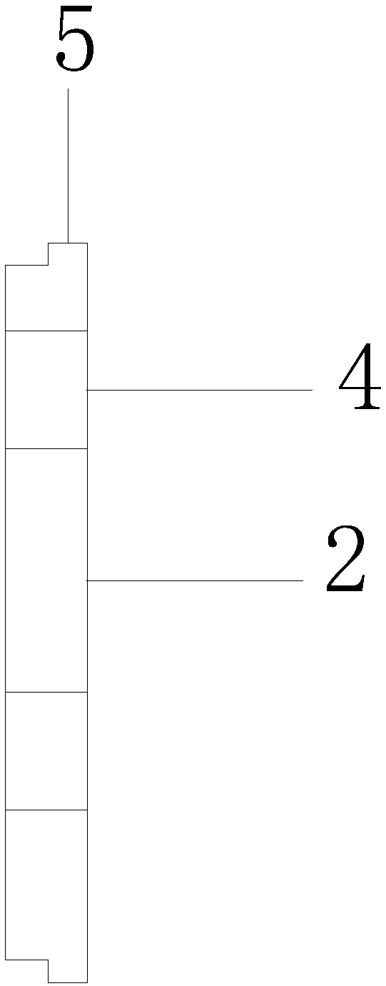
[0015] Such as figure 1 As shown, the charging gun protection structure of the new energy electric vehicle includes a charging gun head 3 for charging the new energy electric vehicle. The front end of the charging gun head 3 is provided with a sliding cavity 8, one of which is The side opening, the front end of the charging gun head 3 is provided with more than one first assembly hole 6, the first assembly hole 6 is matched with the charging interface of the new energy electric vehicle, each first assembly hole is provided with a terminal 1, and the sliding cavity 8 is loaded with a movable piece 2, and the movable piece 2 is provided with a second assembly hole 4 having the same number as the first assembly hole 6, and the first assembly hole 6 and the second assembly hole 4 are exposed in the first assembly hole terminal 1.

[0016] Among them, such as figure 2 As shown, when the second assembly hole 4 and the first assembly hole 6 are staggered, the movable piece 2 seals...


PUM


Abstract

The invention discloses a rechargeable gun protective structure of a novel energy electric vehicle. The rechargeable gun protective structure comprises a rechargeable gun head which is used for charging a novel energy electric vehicle, wherein the front end surface of the rechargeable gun head is provided with a sliding cavity, and one side of the sliding cavity is provided with an opening; the front end surface of the rechargeable gun head is provided with one or more first assembly holes, and the first assembly holes are matched with a charging interface of the novel energy electric vehicle;each first assembly hole is provided with a terminal; and a movable plate is installed in the sliding cavity, the movable plate is provided with second assembly holes with the same quantity with thefirst assembly holes, and when the first assembly holes are right opposite to the second assembly holes, the terminal in the first assembly hole is exposed. By adopting the charger protection structure, the problem that the rechargeable gun head needs a protection cover in the prior art can be solved, after the use, as long as the movable plate is shifted, and the first assembly holes are staggered to the second assembly holes, so that the terminals inside the assembly holes can be protected in a sealing manner.

Description

technical field [0001] The invention relates to the field of new energy vehicles, in particular to a protective structure for a charging gun of a new energy electric vehicle. Background technique [0002] The new energy electric vehicle is charged through the charging pile, and the charging pile is inserted into the charging interface of the electric vehicle through the charging gun. The head of the charging gun is provided with more than one terminal and an assembly hole. The assembly hole is used for matching the charging interface, and the terminal is inserted into the charging port. The power transmission is completed in the jack, however, the charging gun terminal has the risk of water entering when not in use, and external objects will damage the terminal, so the traditional method is to set a protective cover outside the charging gun to protect each terminal through the protective cover , but after the protective cover is installed, the entire protective cover is a se...

Claims


Application Information

Patent Timeline
Patent Type & Authority Applications(China)
IPC IPC(8): H01R13/52B60L11/18
CPCB60L53/31H01R13/5213H01R2201/26Y02T10/70Y02T10/7072Y02T90/12
Inventor 黄国华
Owner 黄国华
Learn More