PLC shunt with good heat dissipation performance

A splitter and heat dissipation technology, which is applied in the field of PLC splitters, can solve the problems affecting the stability of the splitter's working efficiency and life, so as to improve the use effect and service life, reduce the working heat, and accelerate the heat dissipation. speed effect

Pending Publication Date: 2018-02-09
江苏天兴光电科技有限公司
View PDF5 Cites 0 Cited by
  • Summary
  • Abstract
  • Description
  • Claims
  • Application Information

AI Technical Summary

Problems solved by technology

The PLC splitter is compact in structure, small in size, and easy to install. However, in the process of use, the problem of heat dissipation is often not considered. It is basically natural heat dissipation, which often affects the working efficiency and stability of the splitter. It will also affect its life to a certain extent, so it is necessary to consider the heat dissipation function of the PLC splitter

Method used


Image

  • PLC shunt with good heat dissipation performance
  • PLC shunt with good heat dissipation performance
  • PLC shunt with good heat dissipation performance

Examples


Embodiment Construction

[0017] In order to make the technical means, creative features, goals and effects achieved by the present invention easy to understand, the present invention will be further described below in conjunction with specific embodiments.

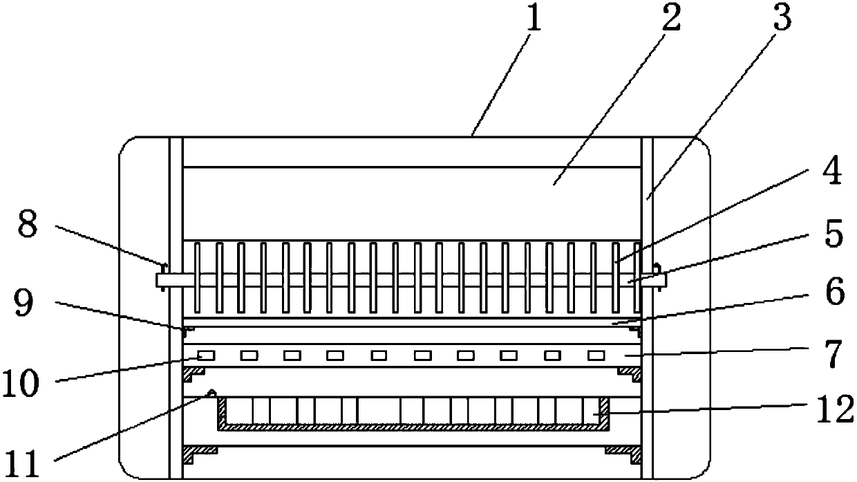
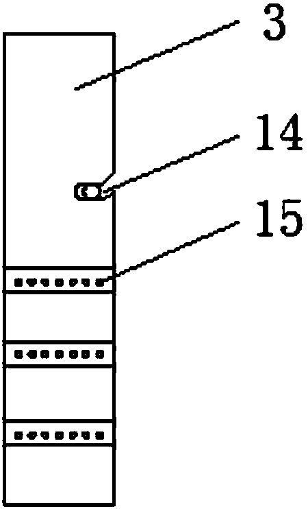
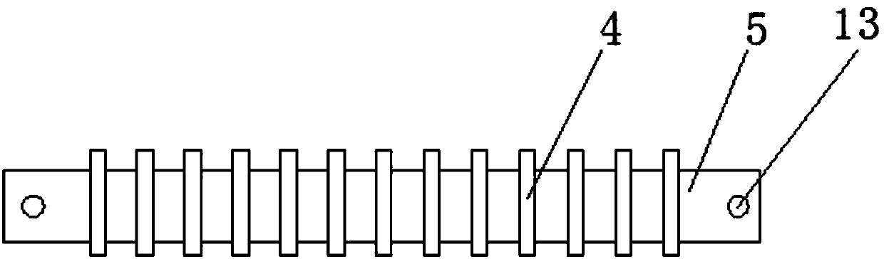
[0018] Such as Figure 1-3 As shown, a PLC splitter with good heat dissipation includes a box body 1, brackets 3 are fixed on both sides inside the box body 1, a fan 12 is fixed on the middle bottom of the box body 1, and the fan 12 The upper surface of the fan 12 is embedded with a temperature sensor 11, a splitter 7 is fixed above the fan 12, and an adapter interface 10 is opened on one side of the splitter 7, and the upper side of the splitter 7 is fixedly connected by screws. There is an intermediate plate 6, a connecting pipe 5 is clamped on the upper side of the intermediate plate 6, and a heat sink 4 is welded on the surface of the connecting pipe 5, and the upper part of the heat sink 4 is embedded in the gap between the top of the box bod...


PUM


Abstract

The invention discloses a PLC shunt with good heat dissipation performance. The PLC shunt comprises a box body. Brackets are fixed to both inner sides of the box body. A fan is fixed to the middle bottom of the box body. A temperature sensor is embedded in the upper surface of the fan. A shunt is fixed above the fan. An adapter interface is arranged on a side of the shunt. An intermediate board isfixedly connected with the upper part of the shunt by a screw. A connecting pipe is stuck in the top of the intermediate board. Cooling fins are soldered on the surface of the connecting pipe. A heatcollecting sheet is embedded in a gap between the upper part of the cooling fins and the top end of the box body. Buckles are fixed to both ends of the connecting pipe. Support feet are fixed to thebottoms of the shunt and the fan. The PLC shunt has the advantages of reasonable design and convenient use. The cooling fins and the fan are good solutions to the situation that the PLC shunt is not easy to cool when used. The shunt is reasonable in installation and compact in structure and has a sense of depth.

Description

technical field [0001] The invention relates to the technical field of splitter heat dissipation, in particular to a PLC splitter with good heat dissipation. Background technique [0002] An optical splitter, also known as an optical splitter, is one of the important passive components in an optical fiber link. It is an optical fiber junction device with multiple input ports and multiple output ports. According to the light splitting principle, the optical splitter can be divided into two types: fusion tapered type and planar waveguide type (PLC type). The PLC splitter is compact in structure, small in size, and easy to install. However, in the process of use, the problem of heat dissipation is often not considered. It is basically natural heat dissipation, which often affects the working efficiency and stability of the splitter. To a certain extent, it will also affect its life. For this reason, the heat dissipation function of the PLC splitter needs to be considered. Co...

Claims


Application Information

Patent Timeline
Patent Type & Authority Applications(China)
IPC IPC(8): G02B6/44
CPCG02B6/44G02B6/4431
Inventor 李国荣
Owner 江苏天兴光电科技有限公司
Why Eureka
Try Eureka