
Movement transmission device, in particular for a robot arm

A transmission and motion technology, applied in transmissions, friction transmissions, manipulators, etc., can solve complex, difficult, expensive and other problems, and achieve the effect of simplified shape, good precision, and simplified machining

Inactive Publication Date: 2018-02-06
MIP ROBOTICS
View PDF8 Cites 0 Cited by
  • Summary
  • Abstract
  • Description
  • Claims
  • Application Information

AI Technical Summary

Problems solved by technology

The disadvantage of this device is that it is particularly complex and expensive, since it requires two crowns and one or more three-armed rotors
In addition, there is considerable friction between the pin and the notch of the crown, which is detrimental
and it is difficult to provide reduced clearance in motion transmission

Method used


Image

  • Movement transmission device, in particular for a robot arm
  • Movement transmission device, in particular for a robot arm
  • Movement transmission device, in particular for a robot arm

Examples


Embodiment Construction

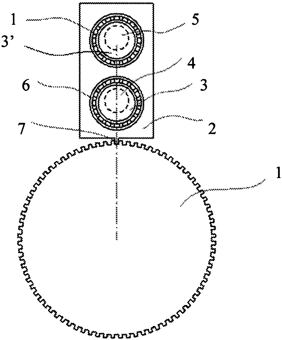
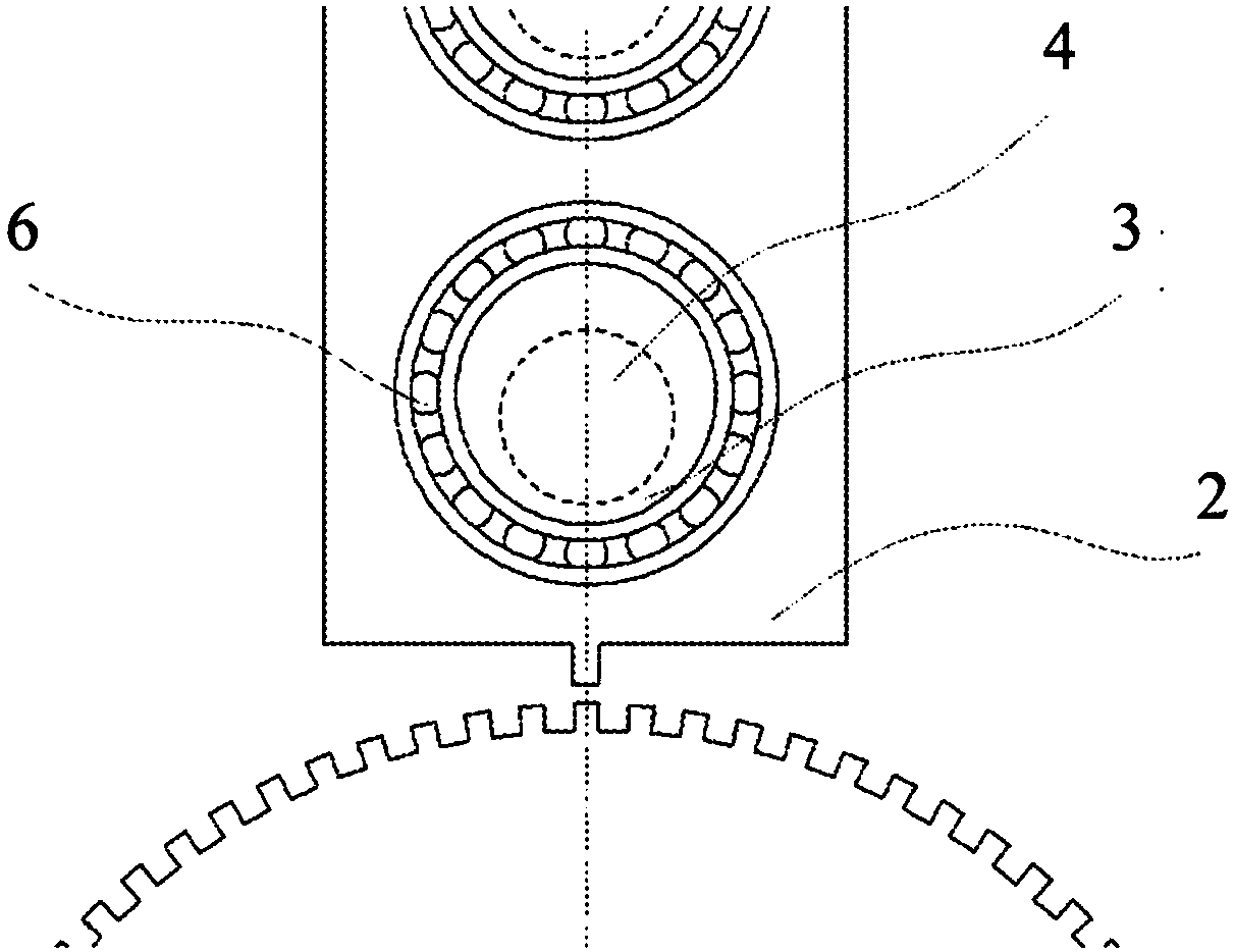
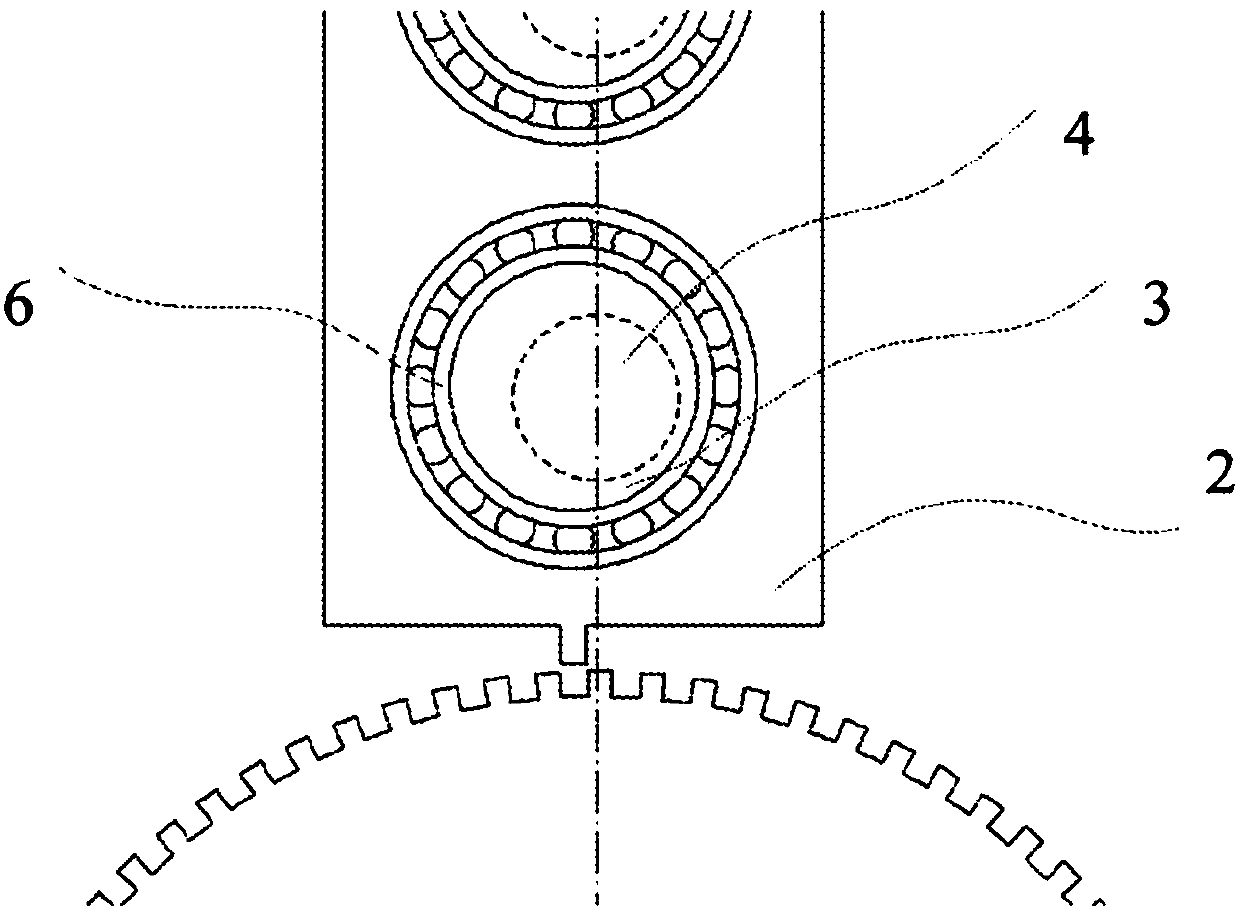
[0037] refer to Figures 1 to 7, the basic principle of the invention will be explained in the case of the wheel having a notch made on its outer periphery, but it also applies to the case where the crown has a notch made on its inner peripheral surface or even Applies to the rack case. Such as figure 1 As shown, the reducer includes an output shaft ( Figures 1 to 7 not shown), the shaft 4 and the arm 2 for motion transmission between the shaft 4 and the wheel 1 . The wheel 1 comprises a series of notches on its outer surface. The number of notches is a function of the desired reduction ratio, eg for a reduction ratio of 1 / 80 there are 80 notches. The arm 2 is preferably mounted on a cylindrical bearing 3 of the shaft 4 by means of a ball bearing 6 or a flat washer. The cylindrical bearing 3 has a slight eccentricity with respect to the axis of rotation of the shaft 4 . Part 2 , comprising teeth 7 incorporated in recesses of wheel 1 , is preferably mounted on cylindric...


PUM


Abstract

The device comprises a shaft 4, a notched mobile member - for example a wheel 1 - and at least three arms 2.1, 2.2, 2.3 that together transmit movement between the shaft 4 and the mobile member. Eacharm is hinged to two eccentric bearings 3, 3' that hold same parallel to said arm, regardless of the rotational angle of the shaft 4 with which they rotate synchronously. Each arm engages with the notches of the wheel 1 during at least a portion of the cyclic motion of same, by means of at least one tooth 7 of the arm, in such a way as to ensure mutual displacement. The bearings 3, 3' are arrangedsuch that at least one of the arms engages with the mobile member, regardless of the rotational angle of the shaft 4. Said device can be used for producing low-clearance speed reducers.

Description

technical field [0001] The invention relates to motion transmissions, in particular for robotic arms. Background technique [0002] The reduction ratio between the electric motor and the robotic arm is about 1 / 100 - typically 1 / 50 to 1 / 200 - where the motor speed is 3000rpm or 50rps and the arm is 0.5rps. [0003] Most current robots use cycloidal type reducers with gears mounted in crowns and with very similar tooth counts, eg 80 and 79 teeth. The crown has internal teeth and a wheel with external teeth. In order to produce a bi-directional and wear-resistant minimum backlash reducer, the teeth must be made of very hard metal and machined with high precision. Crowns with internal teeth are particularly difficult to machine and this involves considerable costs. The high price of the robot is mainly due to the cost of the reducer, and the standard robot includes 6 reducers. In addition, US 5,351,568 discloses a reducer comprising a crown with internal teeth and four arms ...

Claims


Application Information

Patent Timeline
IPC IPC(8): F16H27/04F16H29/12
CPCF16H27/04F16H29/12F16H25/06F16H27/08F16H19/04B25J9/102
Inventor F·O·洛里奥特
Owner MIP ROBOTICS
Learn More