Installation frame for bearing air conditioner outdoor unit

A technology of an air conditioner external unit and a mounting frame, which is applied in the field of mounting frames for carrying an air conditioner external unit, which can solve problems such as inconvenient operation, limited space inside a cavity, and limited cavity space, and achieve stable and reliable installation, reduce labor consumption, and reduce friction. small force effect

Inactive Publication Date: 2018-02-06
成都毅诚机电工程有限公司
View PDF0 Cites 0 Cited by
  • Summary
  • Abstract
  • Description
  • Claims
  • Application Information

AI Technical Summary

Benefits of technology

This technology allows an external unit (air conditioner) inside the house's cabinets with windows without being attached to it when they are maintained or repaired. It also makes sure there is no moving parts between them during movement.

Problems solved by technology

The technical problem addressed by this patented technology relates to maintaining an efficient way to install or service an indoor units (indoor heat pump) inside buildings without having them take up too much room when they're being installed on top due to their weight.

Method used


Image

  • Installation frame for bearing air conditioner outdoor unit
  • Installation frame for bearing air conditioner outdoor unit

Examples


Embodiment Construction

[0011] The present invention will be described in further detail below through specific implementation examples and in conjunction with the accompanying drawings.

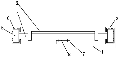
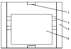
[0012] figure 1 , figure 2 It shows the installation frame for carrying the external unit of the air conditioner provided by the present invention, including the base plate 1, the slide rails 2 located on the left and right sides of the base plate 1 parallel to each other, the carrier plate 3 located above the base plate 1, and two brackets fixed at the lower end of the carrier plate 3 Shifting shaft 4; the section of the sliding rail 2 is C-shaped, and the C-shaped openings of the two sliding rails 2 are opposite; the two shifting shafts 4 are perpendicular to the sliding rail 2, and the two ends of the shifting shaft 4 extend into the slide rails on both sides respectively. Rail 2; both ends of the two moving shafts 4 are fixed with a rectangular block 5 corresponding to the slide rail 2, and the surface of the...


PUM


Abstract

The invention discloses a mounting frame for carrying an external unit of an air conditioner, belonging to the technical field of air conditioner installation, comprising a bottom plate, sliding rails located on the left and right sides of the bottom plate parallel to each other, a carrier plate located above the bottom plate, and two sliding rails fixed at the lower end of the carrier plate. shaft; the section of the slide rail is C-shaped, and the C-shaped openings of the two slide rails are opposite; the two shift shafts are perpendicular to the slide rails, and the two ends of the shift shaft extend into the slide rails on both sides; the two shift shafts Both ends are fixed with a rectangular block corresponding to the slide rail, and the surface of the rectangular block is provided with a plurality of steel balls that are respectively in contact with the inner walls of the slide rail opening; the middle of the front and rear ends of the bottom plate is provided with a limit block, and two shifting shafts The middle part of the lower end of each is provided with a positioning block corresponding to the limiting block; the top surface of the limiting block is higher than the bottom surface of the positioning block. Easy maintenance, stable and reliable installation, labor-saving operation, reducing labor consumption of the operator.

Description


Claims


Application Information

Patent Timeline
Owner 成都毅诚机电工程有限公司
Why Eureka
Try Eureka