
Controllable mechanism type drilling robot

A robot and mechanism technology, applied in drilling/drilling equipment, program-controlled manipulators, manipulators, etc., can solve the problems of difficult to meet high-speed and high-precision positioning, poor mechanism dynamic performance, joint error accumulation, etc., and achieve stiffness and weight. The effect of large ratio, large motion space and small error accumulation

Inactive Publication Date: 2018-02-06
GUANGXI PROVINCE NANNING CITY XUXI TECH CO LTD
View PDF0 Cites 0 Cited by
  • Summary
  • Abstract
  • Description
  • Claims
  • Application Information

AI Technical Summary

Problems solved by technology

However, due to the limitations of its own structure, this type of traditional open-chain series robot mechanism requires the motor to be installed at the joint, which will lead to problems such as heavy arm weight, poor rigidity, large inertia, joint error accumulation, and poor dynamic performance of the mechanism. It is difficult to meet the requirements of high-speed high-precision positioning, multi-angle adjustable drilling operations, etc.

Method used


Image

  • Controllable mechanism type drilling robot
  • Controllable mechanism type drilling robot
  • Controllable mechanism type drilling robot

Examples


Embodiment 1

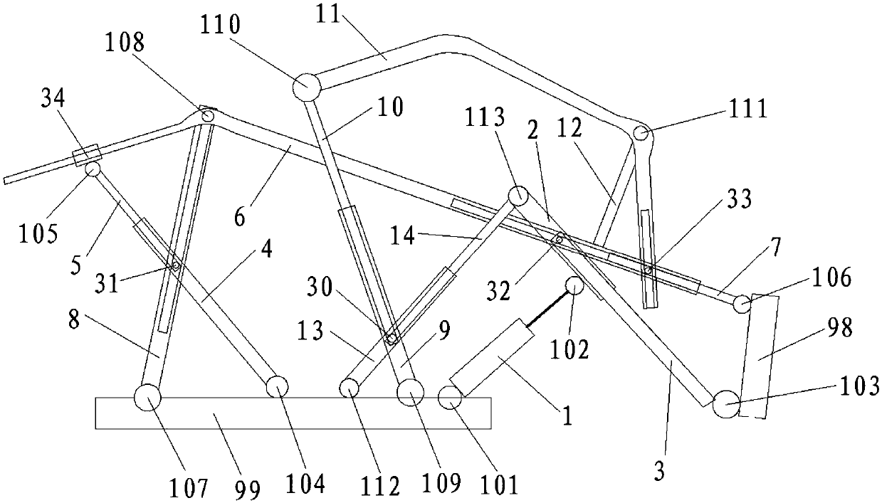
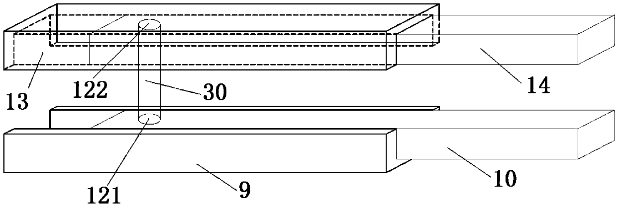
[0031] Controllable mechanism drilling robot, including pole one 1, pole two 2, pole three 3, pole four 4, pole five 5, pole six 6, pole seven 7, pole eight 8, pole nine 9, pole ten 10, pole Eleven 11, rod twelve 12, rod thirteen 13, rod fourteen 14, shaft rod 30, first cylindrical pin 31, second cylindrical pin 32, third cylindrical pin 33, sliding sleeve 34, actuator 98 and machine Rack 99,

[0032] One end of the rod ten 10 three 13 is connected to the frame 99 through the rotating pair twelve 112, the other end of the rod ten 10 three 13 is connected with one end of the rod fourteen 14 through the axial movement pair to form a telescopic rod, and the other end of the rod fourteen 14 is rotated Pair 13 113 is connected to one end of rod 2 2, the other end of rod 2 2 is connected to one end of rod 3 3 through an axial movement pair to form a telescopic rod, the other end of rod 3 3 is connected to actuator 98 through rotating pair 3 103, and one end of the oil cylinder It i...


PUM


Abstract

Controllable mechanism drilling robot, one end of rod 13 is connected to the frame and the other end is connected to one end of rod 14 through an axial movement pair, the other end of rod 14 is connected to one end of rod 2, and the other end of rod 2 is passed through The axial movement pair is connected to one end of rod three, the other end of rod three is connected to the actuator, one end of rod four is connected to the frame, and the other end is connected to one end of rod five through the axial movement pair, and the other end of rod five is connected to On the sliding sleeve, the sliding sleeve is set on one end of rod six, the other end of rod six is ​​connected to one end of rod seven through an axial movement pair, the other end of rod seven is connected to the actuator, and one end of rod nine is connected to the other end of the frame The other end of rod ten is connected with one end of rod eleven. The other end of rod eleven is provided with an axial chute. One end of the shaft is connected to rod ten through a rotating pair. The other end is connected on the bar 14 by a rotary joint.

Description

technical field [0001] The invention relates to the mechanical field, in particular to a controllable mechanism drilling robot. Background technique [0002] A drilling robot is a machine device that performs work automatically, and is a machine that realizes various functions by its own power and control capabilities. It can accept human intelligence, or it can execute according to pre-programmed programs. Drilling robots can replace humans in some monotonous, frequent and repetitive long-term operations in industrial production, or precision machining and other operations that require high precision. They are widely used in machining and production assembly processes, as well as in coal mines, etc. In workplaces with many obstacles and harsh environmental conditions. Existing drilling robots basically belong to joint robots, which have been widely used because of their larger working space and more flexible movements. However, due to the limitations of its own structure...

Claims


Application Information

Patent Timeline
IPC IPC(8): B25J11/00B25J9/00B25J9/12B23B47/00
CPCB25J11/005B23B47/00B25J9/00B25J9/12
Inventor 不公告发明人
Owner GUANGXI PROVINCE NANNING CITY XUXI TECH CO LTD
Learn More