
Buried type anti-flood wall driven by lifting push rod

An embedded flood control wall technology, applied in dikes, coastline protection, dams, etc., can solve problems such as technical difficulties, insufficient estimation, poor water retaining effect, etc., and achieve suitable for popularization and application, simple structure, and good use effect Effect

Active Publication Date: 2018-02-02
NORTH CHINA UNIV OF WATER RESOURCES & ELECTRIC POWER
View PDF2 Cites 9 Cited by
  • Summary
  • Abstract
  • Description
  • Claims
  • Application Information

AI Technical Summary

Problems solved by technology

In most urban areas of our country, there are frequent rainstorms in summer. Due to short-term heavy rains, urban waterlogging also occurs from time to time, especially in underground garages and other underground spaces. Due to the inability to block rainwater in time, a large number of vehicles and other facilities are flooded, causing huge damage. loss of property, often endangering people's lives
The reason is that, on the one hand, the development of urbanization has caused more and more heavy rains in recent years, and the drainage design for waterlogging in heavy rains is insufficiently estimated; on the other hand, there are also technical difficulties, making it difficult to prevent Measures, such as using sandbags in advance to block the water flow and prevent it from flowing into the underground space from the entrance and exit, but this method has low efficiency, poor water blocking effect, and high demolition cost

Method used


Image

  • Buried type anti-flood wall driven by lifting push rod
  • Buried type anti-flood wall driven by lifting push rod
  • Buried type anti-flood wall driven by lifting push rod

Examples


Embodiment 2

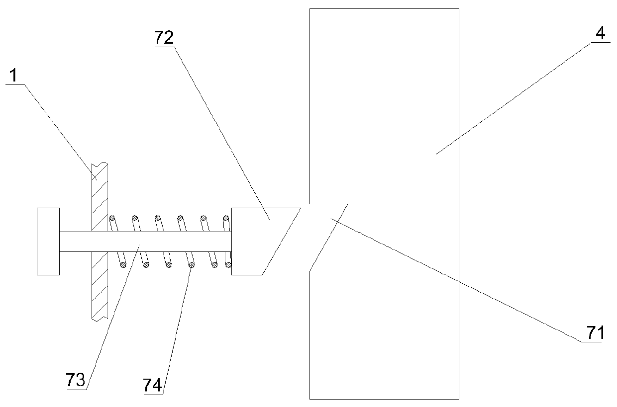
[0025] Example 2: see image 3 : the automatic locking mechanism includes a wedge-shaped card table with a wide top and a narrow bottom, a guide rod is connected to the rear side of the wedge-shaped card table, a compression spring is set on the guide rod, and a wedge-shaped card slot is arranged on the side of the lifting push rod 4, The wedge-shaped clamping table can be matched and inserted into the wedge-shaped clamping groove, and the rear end of the compression spring is pressed against the concrete foundation or on a support pre-embedded in the concrete foundation.

Embodiment 3

[0026] Embodiment 3: see Figure 4 and Figure 5 , the hidden bolt 16 arranged in the dark groove, its rotating shaft is located at the lower end of the hidden bolt 16 and close to the bottom of the groove, the upper end of the hidden bolt 16 is inclined outwards and fitted on the inner wall of the dark groove cover plate 18, the center of gravity of the hidden bolt 16 Located on the outside of the rotating shaft, the dark groove cover plate 18 is a push-pull type, and slideways fixed on the wall are arranged on the upper and lower sides of the dark groove cover plate 18 .

Embodiment 4

[0027] Embodiment 4: see Image 6 , The water retaining plate includes a shell and an embedded expansion plate, and the two sides of the expansion plate are conveniently provided with hidden elastic edge banding.


PUM


Abstract

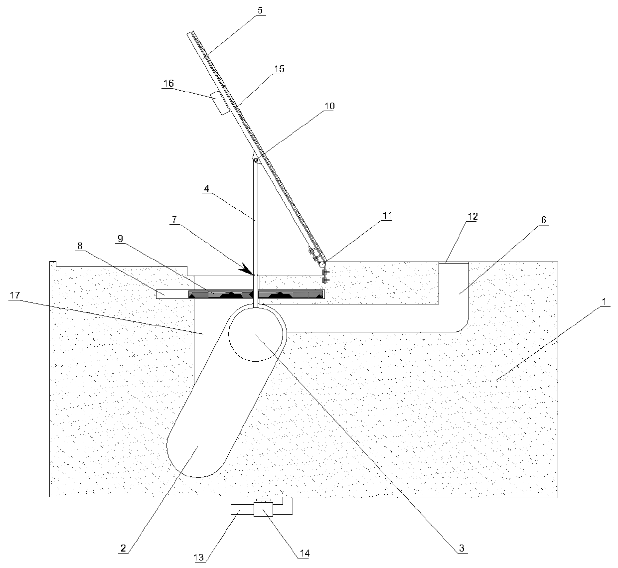
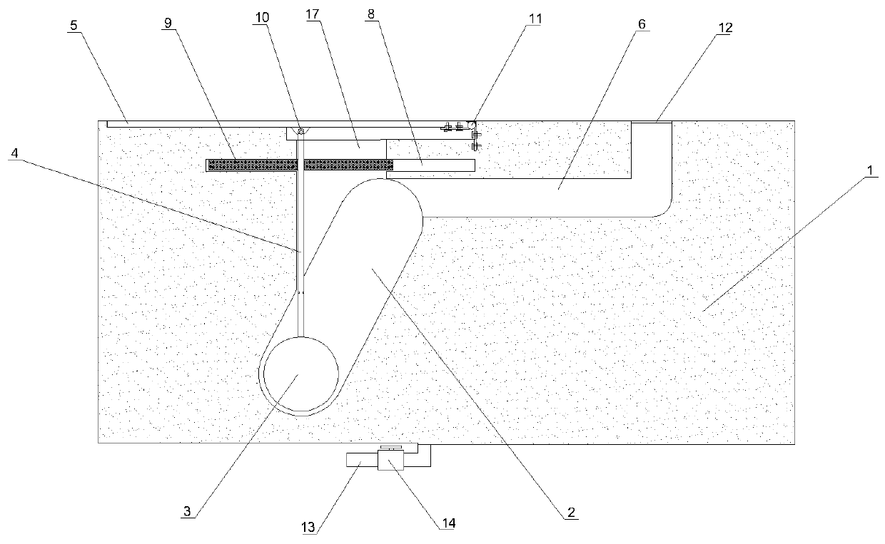
The invention discloses a buried type anti-flood wall driven by a lifting push rod. The buried type anti-flood wall comprises a water stopping plate, a lower rotary shaft and a supporting mechanism. The water stopping plate is hinged to the surface of a foundation, and the supporting mechanism is arranged on the backwater side of the water stopping plate. A ground leakage channel is formed in oneside of the upstream face of the water stopping plate, a floating ball slideway and a push rod receding area are arranged below the water stopping plate, and the floating ball slideway communicates with the ground leakage channel. The lifting push rod is fixed to the middle of a cross slide block in a penetrating mode, and a water draining pipe is arranged at the bottom of the push rod receding area or the floating ball slideway. The buried type anti-flood wall can be in a hidden state at a normal non-flood stage, and normal using of the channel is not influenced. When flood comes, after onlya small amount of flood enters a ground leakage at the early stage, the floating ball slideway can be filled with water, and under the buoyancy of floating balls, the water stopping plate is driven tobe unfolded upwards, thus the effects of flood resisting and preventing are achieved, and the buried type anti-flood wall is good in using effect and extremely suitable for being applied and popularized.

Description

technical field [0001] The invention belongs to the technical field of basement flood control equipment, and in particular relates to an embedded flood control wall driven by a lifting push rod. Background technique [0002] In our country, with the continuous improvement of the level of science and technology, people's lives have been well guaranteed. In existing urban flood control projects, there are many flood control devices. In most urban areas of our country, there are frequent rainstorms in summer. Due to short-term heavy rains, urban waterlogging also occurs from time to time, especially in underground garages and other underground spaces. Due to the inability to block rainwater in time, a large number of vehicles and other facilities are flooded, causing huge damage. Property damage often endangers people's lives. The reason is that, on the one hand, the development of urbanization has caused more and more heavy rains in recent years, and the drainage design for ...

Claims


Application Information

Patent Timeline
IPC IPC(8): E02B3/10
Inventor 张宏洋丁泽霖梁士奎张先起
Owner NORTH CHINA UNIV OF WATER RESOURCES & ELECTRIC POWER
Learn More