Movable overhead viaduct anti-collision wall construction platform and construction method thereof

A technology of construction platform and anti-collision wall, applied in the direction of erecting/assembling bridges, bridges, bridge parts, etc., can solve problems such as hidden safety hazards and difficult construction of anti-collision walls, and achieve the effect of construction safety, construction quality assurance, and convenient use.

Inactive Publication Date: 2018-02-02
CHINA MCC17 GRP
View PDF4 Cites 1 Cited by
  • Summary
  • Abstract
  • Description
  • Claims
  • Application Information

AI Technical Summary

Problems solved by technology

At present, there are anti-collision walls on both sides of the viaduct design. After the construction of the bridge anti-collision walls, due to the limitation of construction conditions, it is difficult to construct part of the anti-collision walls, which sometimes consumes a lot of manpower and material resources and causes great damage. Security risks

Method used


Image

  • Movable overhead viaduct anti-collision wall construction platform and construction method thereof
  • Movable overhead viaduct anti-collision wall construction platform and construction method thereof

Examples


Embodiment 1

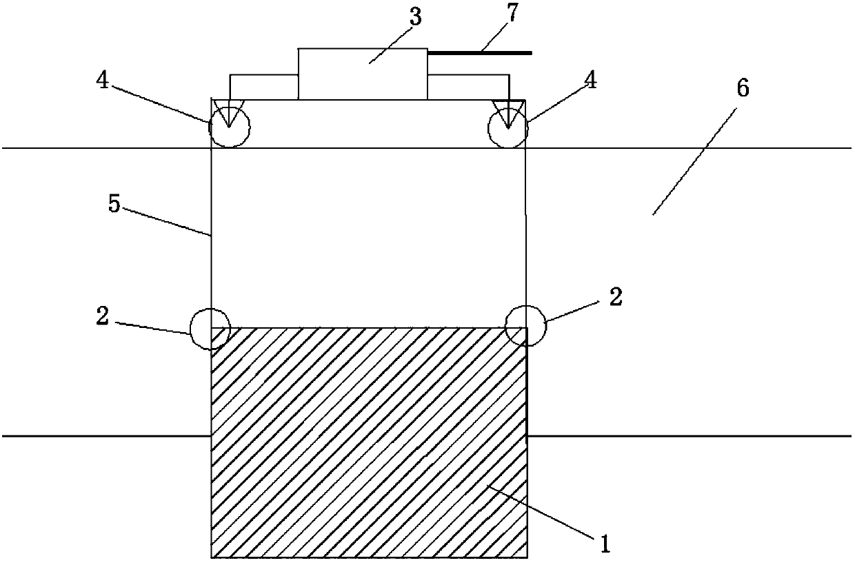
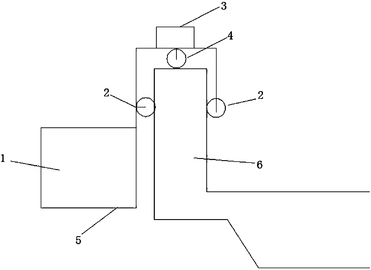
[0016] see Figure 1 ~ Figure 2 , the present invention provides a technical solution: a movable viaduct anti-collision wall construction platform, comprising: a motor 3, pulleys, wires 7, switches, an operating platform 1, a safety belt, and the pulleys include side pulleys 2 and walking Wheel 4, the operating platform 1 includes a running mechanism and an operating mechanism, the running mechanism is n-type, the operating mechanism is a cuboid or cube structure, the lower side of the walking mechanism is fixedly connected to the upper side of the operating mechanism, and the A side pulley 2 is provided between the side of the traveling mechanism and the anti-collision wall of the viaduct, a traveling wheel 4 is provided between the upper surface of the inner side of the traveling mechanism and the anti-collision wall of the viaduct, and a motor 3 is arranged above the traveling mechanism. The motor 3 is connected to the walking wheel 4 by a belt or through a gearbox, the mot...

Embodiment 2

[0019] see Figure 1 ~ Figure 2 , the present invention provides a technical solution: a movable viaduct anti-collision wall construction platform, comprising: a motor 3, pulleys, wires 7, switches, an operating platform 1, a safety belt, and the pulleys include side pulleys 2 and walking Wheel 4, the operating platform 1 includes a running mechanism and an operating mechanism, the running mechanism is n-type, the operating mechanism is a cuboid or cube structure, the lower side of the walking mechanism is fixedly connected to the upper side of the operating mechanism, and the A side pulley 2 is provided between the side of the traveling mechanism and the anti-collision wall of the viaduct, a traveling wheel 4 is provided between the inner upper surface of the traveling mechanism and the anti-collision wall of the viaduct, and a motor 3 is arranged above the traveling mechanism. The motor 3 is connected to the walking wheel 4 by a belt or through a gearbox, the motor 3 is conn...


PUM


Abstract

The invention discloses a construction platform for a movable anti-collision wall of a viaduct and a construction method thereof. The construction platform for a movable anti-collision wall of an viaduct includes: a motor, a pulley, an electric wire, a switch, an operating platform, and a safety belt, The pulley includes a side pulley and a walking wheel, and the operating platform includes a traveling mechanism and an operating mechanism. The traveling mechanism is n-shaped, and the operating mechanism is a cuboid or cube structure. One side is fixed on the upper side, side pulleys are provided between the side of the walking mechanism and the anti-collision wall of the viaduct, walking wheels are provided between the upper surface of the inner side of the traveling mechanism and the anti-collision wall of the viaduct, and above the traveling mechanism Motor, the motor is connected to the traveling wheels through a belt or through a gearbox, the motor is connected to a switch through a wire, the switch is connected to an external power supply through a wire, the switch is arranged on the running mechanism, and the safety belt is arranged on on the operating mechanism.

Description

technical field [0001] The invention belongs to the technical field of bridge construction in highway and railway engineering, in particular to a movable anti-collision wall construction platform for viaducts and a construction method thereof. Background technique [0002] The construction of the viaduct is conducive to the environment of urban traffic pressure, and has a very good role in promoting the development of the national economy. At present, there are anti-collision walls on both sides of the viaduct design. After the construction of the bridge anti-collision walls, due to the limitation of construction conditions, it is difficult to construct part of the anti-collision walls, which sometimes consumes a lot of manpower and material resources and causes great damage. Security risks. The construction platform object that the present invention proposes is to solve this problem. Contents of the invention [0003] The technical problem to be solved by the present in...

Claims


Application Information

Patent Timeline
Patent Type & Authority Applications(China)
IPC IPC(8): E01D19/10E01D21/00
CPCE01D19/106E01D21/00
Inventor 张持鹏詹波立赵凯郑军强
Owner CHINA MCC17 GRP
Why Eureka
Try Eureka