Composite insulating member, manufacturing method thereof, and electrical device having the composite insulating member

A technology of composite insulation and insulating components, which is applied in the direction of insulated cables, insulated conductors, electrical components, etc., can solve the problems of reduced output of electrical devices, shortened life of electrical devices, and limited heat transfer performance, so as to suppress excessive temperature rise and promote conductors. Excellent heat transfer and heat transfer effects

Active Publication Date: 2019-06-18
LG MAGNA E POWERTRAIN CO LTD
View PDF5 Cites 0 Cited by
  • Summary
  • Abstract
  • Description
  • Claims
  • Application Information

AI Technical Summary

Problems solved by technology

[0009] However, for an electrical device having such an existing insulating member 40, since the thermal conductivity of the insulating member 40 is relatively low, the heat generated by the stator coil 25 cannot pass through quickly during operation. The insulating member 40 , thereby causing a temperature rise inside the insulating member 40 , that is, the stator coil 25
[0010] When the temperature of the stator coil 25 rises, the resistance increases, thereby reducing the output of the electric device (motor).
[0011] In addition, the high temperature of the stator coil 25 promotes forced deterioration of the electrical device, thereby shortening the life of the electrical device
[0012] In view of such a problem, a method of applying silicone resin to both surfaces of the insulating member 40 has been proposed in some prior art, but since the thermal conductivity of the insulating member 40 is low, there is a limit to improving the heat transfer performance.
[0013] In addition, an insulating method using a silicone resin has been proposed in some prior art. However, the shape-maintaining strength of the silicone resin is insufficient due to the characteristics of the material, so it cannot be used like a general insulating member 40 (eg, "Nomex"). "Insulation paper) is bent and formed, so there is a problem that it is difficult to apply it to the product and use it.

Method used


Image

  • Composite insulating member, manufacturing method thereof, and electrical device having the composite insulating member
  • Composite insulating member, manufacturing method thereof, and electrical device having the composite insulating member
  • Composite insulating member, manufacturing method thereof, and electrical device having the composite insulating member

Examples


Embodiment Construction

[0065] Hereinafter, embodiments of the present invention will be described in detail with reference to the drawings.

[0066] In this specification, even if it is a different embodiment, the same or similar reference numerals are given to the same or similar structures, and the description thereof will be replaced by the first description. A singular expression used in this specification includes a plural expression unless there is a clear difference in context.

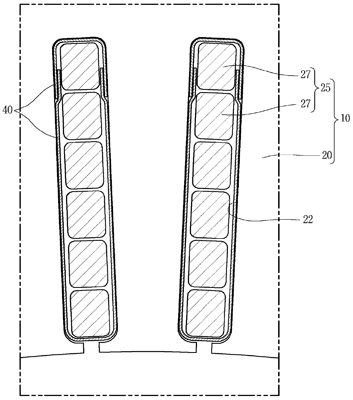
[0067] The present invention relates to a composite insulation member having insulation performance and heat dissipation performance capable of promoting cooling of conductors, a method for manufacturing the composite insulation member, and an electrical device having the composite insulation member.

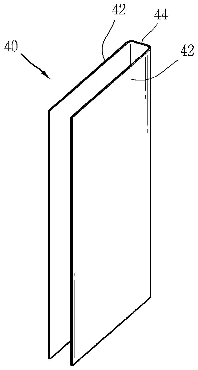
[0068] image 3 It is a cross-sectional view of an electrical device having a composite insulating member according to an embodiment of the present invention, Figure 4 yes image 3 An enlarged view of the main part...


PUM

PropertyMeasurementUnit
thicknessaaaaaaaaaa

Abstract

The present invention relates to a composite insulating member, a method for manufacturing the same, and an electrical device having the composite insulating member. The composite insulating member of the present invention includes: a first insulating member formed of an electrical insulating member having a filling space; and a second insulating member formed of an electrical insulating member having a higher thermal conductivity than the first insulating member. To transfer performance, the second insulating member is filled in the filling space. Thereby, the conductor can be insulated, and the heat dissipation of the conductor can be promoted.

Description

technical field [0001] The present invention relates to a composite insulating member, a method for manufacturing the same, and an electrical device having the composite insulating member. electrical installations. Background technique [0002] As is well known, electric appliances, electrical equipment, or electrical devices (hereinafter, referred to as "electric devices") that use electricity as a power source include electrical conductors and insulating members for insulating the electrical conductors so that power can be supplied. [0003] For example, if figure 1 As shown, the stator 10 of the electric motor includes: a stator core 20 having a slot 22 ; and a stator coil 25 wound on the slot 22 . [0004] Insulating paper or an insulating member 40 (hereinafter referred to as 'insulating member 40') is provided inside the slot 22 of the stator core 20, and then the stator coil 25 is inserted. [0005] Such as figure 2 As shown, the insulating member 40 is bent into...

Claims


Application Information

Patent Timeline
Patent Type & Authority Patents(China)
IPC IPC(8): H01B7/02H01B7/10H01B7/18H01B7/42
CPCH01B3/30H01B7/02H01B7/18H01B7/42H01B7/0216H01B7/104H01B7/421
Inventor 李良洙金在民李正九闵丙旭
Owner LG MAGNA E POWERTRAIN CO LTD
Why Eureka
Try Eureka