Demagnetizing device for automobile parts

A technology for degaussing devices and auto parts, applied to magnetic objects, electrical components, circuits, etc., can solve problems such as low work efficiency, inconvenient installation and disassembly of wire boards, affecting processes, etc., to facilitate installation and disassembly, and avoid manual manual placement. , the effect of improving safety

Inactive Publication Date: 2018-01-26
南宁钛银科技有限公司
View PDF5 Cites 0 Cited by
  • Summary
  • Abstract
  • Description
  • Claims
  • Application Information

AI Technical Summary

Problems solved by technology

[0002] With the continuous development of society and the rapid improvement of people's living standards, more and more cars are manufactured to meet people's travel and other construction requirements. In the manufacturing process of auto parts, parts are also Some magnetism has not been eliminated, which is not conducive to assembly and use. Therefore, it is necessary to eliminate the magnetism on the parts before entering the next process. The current degaussing device is relatively simple, and the parts need to be manually put into the degaussing device. The degaussing process It cannot work continuously, and the work efficiency is low. At the same time, there is no protective device on the traditional degaussing device. Workers are likely to be injured by radiation when they get close, which will cause harm to the human body. Most of the automatic degaussing devices simply put parts on the conveyor belt. Parts are easy to deviate, which affects the process, and the wire plate is not easy to install and disassemble, and it is inconvenient to use. Therefore, there is an urgent need for a degaussing device for auto parts to meet people's needs.

Method used


Image

  • Demagnetizing device for automobile parts
  • Demagnetizing device for automobile parts
  • Demagnetizing device for automobile parts

Examples


Embodiment Construction

[0015] The following will clearly and completely describe the technical solutions in the embodiments of the present invention with reference to the accompanying drawings in the embodiments of the present invention. Obviously, the described embodiments are only some, not all, embodiments of the present invention. Based on the embodiments of the present invention, all other embodiments obtained by persons of ordinary skill in the art without making creative efforts belong to the protection scope of the present invention.

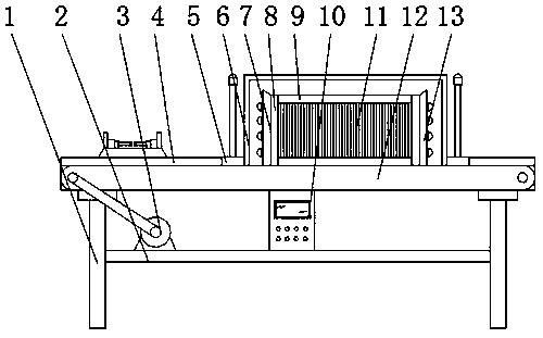
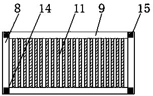
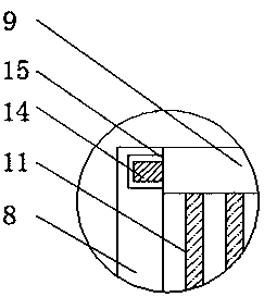
[0016] see Figure 1-4 , an embodiment provided by the present invention: a degaussing device for automobile parts, including a first frame body 1, a lead plate main body 7, a metal wire 11 and a hydraulic telescopic rod 17, and a horizontal plate is fixed at the bottom end of the first frame body 1 2. A motor 3 is installed on one side of the top of the horizontal plate 2. The model of the motor 3 can be Y90S-2. A control panel 10 is installed in the middle o...


PUM


Abstract

The invention discloses a demagnetizing device for automobile parts. The device comprises a first frame body, a main wire plate body, metal wires and hydraulic retractable rods, a transverse plate arefixedly arranged at the bottom end of the first frame body, a motor is installed at one side of the top end of the transverse plate, a control panel is installed in the middle of the top end of the transverse plate, a conveyor belt is installed at the end, close to the motor, of the interior of the frame body, a conveying caterpillar belt is installed on the conveyor belt, one end of the top of the conveying caterpillar belt is provided with a base, fixing plates are installed at the two ends of the top of the base, the hydraulic retractable rods are fixedly arranged between the fixing plates, vertical rods are installed at the two sides of the main wire plate body, clamping blocks matched with clamping grooves are arranged at the two ends of each vertical rod, and the metal wires are evenly fixed between the vertical rods and transverse rods. By means of the demagnetizing device for the automobile parts, through the installation of the hydraulic retractable rods and hoops, the partsdifferent in specification and size can be fixed and demagnetized at the same time without replacing the equipment again.

Description

technical field [0001] The invention relates to the technical field of degaussing devices, in particular to a degaussing device for automobile parts. Background technique [0002] With the continuous development of society and the rapid improvement of people's living standards, more and more cars are manufactured to meet people's travel and other construction requirements. In the manufacturing process of auto parts, parts are also Some magnetism has not been eliminated, which is not conducive to assembly and use. Therefore, it is necessary to eliminate the magnetism on the parts before entering the next process. The current degaussing device is relatively simple, and the parts need to be manually put into the degaussing device. The degaussing process It cannot work continuously, and the work efficiency is low. At the same time, there is no protective device on the traditional degaussing device. Workers are likely to be injured by radiation when they get close, which will cau...

Claims


Application Information

Patent Timeline
Patent Type & Authority Applications(China)
IPC IPC(8): H01F13/00
Inventor 隆成柱
Owner 南宁钛银科技有限公司
Why Eureka
Try Eureka