
Power semiconductor device loss characteristic test platform and method

A technology for power semiconductors and test platforms, applied in instruments, measuring devices, measuring electrical variables, etc., can solve the problems of difficult adjustment of load current, inconsistent device working states, and small number of measurable devices, and achieve accurate switching loss test results, Realize the effect of cycle test and good loss test

Active Publication Date: 2018-01-26
SHANGHAI JIAO TONG UNIV
View PDF8 Cites 25 Cited by
  • Summary
  • Abstract
  • Description
  • Claims
  • Application Information

AI Technical Summary

Problems solved by technology

However, it is often challenging to obtain test results with reference value: first, the test conditions should be as close as possible to the real application environment and operating conditions of the device; second, to reduce the test errors introduced by parasitic parameters in the test circuit, And consider the working environment of the device under test at multiple temperatures, multiple DC voltages, and multiple currents; in addition, because there are certain differences in the performance of different devices of the same model, it is often necessary to test multiple devices to obtain statistical Meaningful Performance Distribution Results
[0004] Existing technologies usually use double-pulse test circuits to extract the switching characteristics of power semiconductor devices, and use I / V curve measuring instruments to extract the conduction characteristics of power semiconductor devices; these traditional methods are difficult to adjust the load current and have large parasitic parameters , needs to be measured separately on different devices, the number of devices that can be tested at one time is small, and the working status of the devices is inconsistent with the actual working conditions, etc., it is difficult to meet the above test requirements

Method used


Image

  • Power semiconductor device loss characteristic test platform and method
  • Power semiconductor device loss characteristic test platform and method
  • Power semiconductor device loss characteristic test platform and method

Examples


Embodiment Construction

[0065] The present invention will be described in detail below in conjunction with specific embodiments. The following examples will help those skilled in the art to further understand the present invention, but do not limit the present invention in any form. It should be noted that those skilled in the art can make several changes and improvements without departing from the concept of the present invention. These all belong to the protection scope of the present invention.

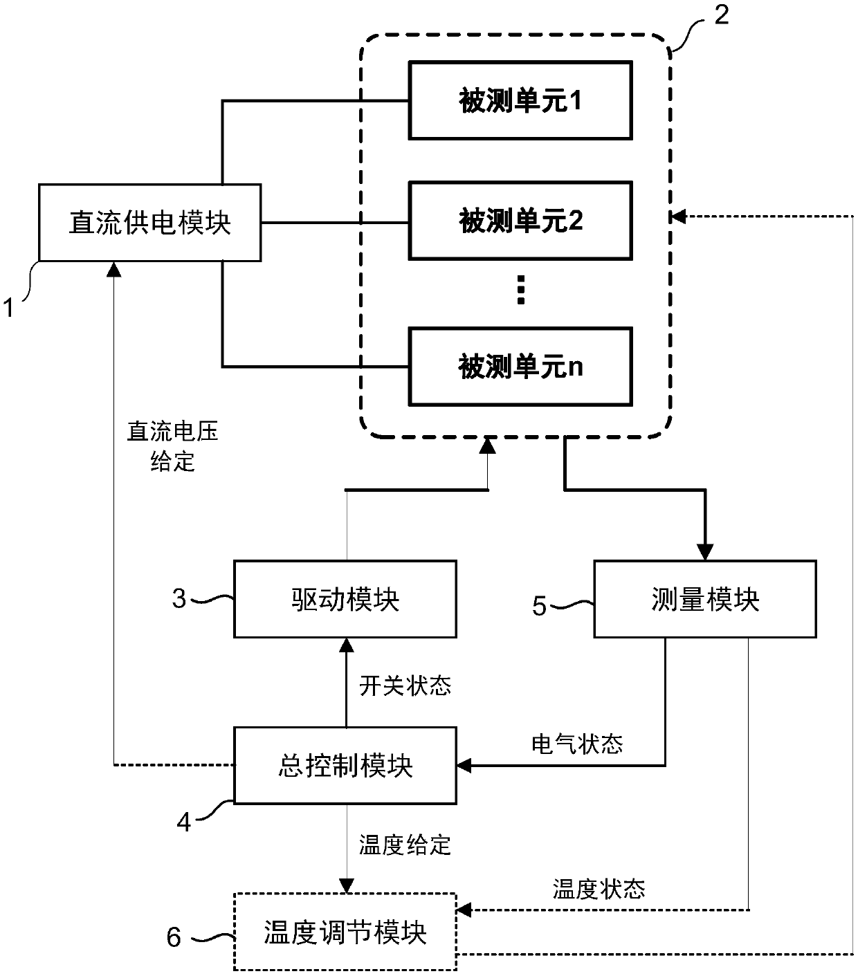
[0066] figure 1 The structure schematic diagram of the test platform of the power semiconductor device loss characteristic provided for the present invention, according to figure 1 As shown, it may include: a DC power supply module 1 , a module under test 2 including at least one unit under test, a drive module 3 , a measurement module 5 , a general control module 4 , or a temperature adjustment module 6 . Wherein, the number of DC output port groups of the DC power supply module 1 is the same as the n...


PUM


Abstract

The invention provides a power semiconductor device loss characteristic test platform and method. The device comprises a DC power supply module used for providing electric energy to a tested module according to a given reference voltage, the tested module comprising at least one tested unit used for simulating a work state of power semiconductor devices, a driving module used for controlling switch states of the power semiconductor devices of the tested unit according to a switch state signal outputted by a main control module, a measurement module used for detecting an electrical state and atemperature state of the power semiconductor devices of the tested unit and a corresponding load module, and the main control module used for analyzing the result measured by the measurement module and controlling the whole test platform to acquire loss characteristics of the power semiconductor devices of the tested unit. The device is advantaged in that switch and state characteristic tests of the multiple power semiconductor devices close to a real work state can be realized, and setting of multiple test conditions including current, voltage and temperature can be carried out.

Description

technical field [0001] The invention relates to the technical field of power electronics and power semiconductor devices, in particular to a testing platform and a testing method for loss characteristics of power semiconductor devices. Background technique [0002] Power semiconductor devices need to withstand large voltage and current stress when they work, and are the most expensive components and main heat sources in power electronic converters. In order to improve the reliability and economy of the converter, it is necessary to accurately predict and evaluate the thermal behavior and working efficiency of the power semiconductor device. Before this, the loss characteristics of the power semiconductor device under the working state must be obtained. [0003] To obtain accurate loss characteristics of power semiconductor devices under working conditions, it is necessary to extract the switching and conduction characteristics of the device. However, it is often challenging...

Claims


Application Information

Patent Timeline
IPC IPC(8): G01R27/26
Inventor 马柯朱晔
Owner SHANGHAI JIAO TONG UNIV
Learn More