
Fixing and moving mechanism for side wall polishing mechanism of bent hardware

A technology of polishing mechanism and moving mechanism, which is applied in the direction of surface polishing machine tools, grinding/polishing equipment, grinding/polishing safety devices, etc., which can solve the problems of manual polishing and parts clamping and fixing, and achieve convenient and automatic The effect of polishing

Inactive Publication Date: 2018-01-26
FOSHAN RUIPUDA OPTOELECTRONICS TECH CO LTD
View PDF0 Cites 5 Cited by
  • Summary
  • Abstract
  • Description
  • Claims
  • Application Information

AI Technical Summary

Problems solved by technology

[0002] After the existing mechanical parts are used for a certain period of time, they will be damaged or the surface will be rough and need to be polished regularly. Generally, the polishing of the plane is very convenient for manual polishing. However, when there are vertical bending parts on both sides of the mechanical parts, When the inner wall of the vertical bending part needs to be polished, manual polishing is very troublesome, and people need to move to polish different positions of the parts, and it is troublesome to clamp and fix such parts

Method used


Image

  • Fixing and moving mechanism for side wall polishing mechanism of bent hardware
  • Fixing and moving mechanism for side wall polishing mechanism of bent hardware

Examples


Embodiment

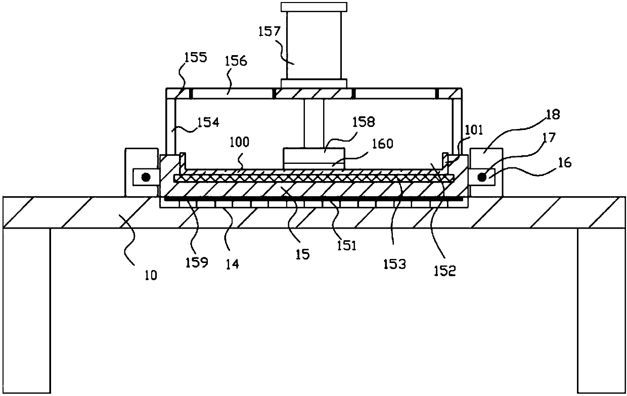
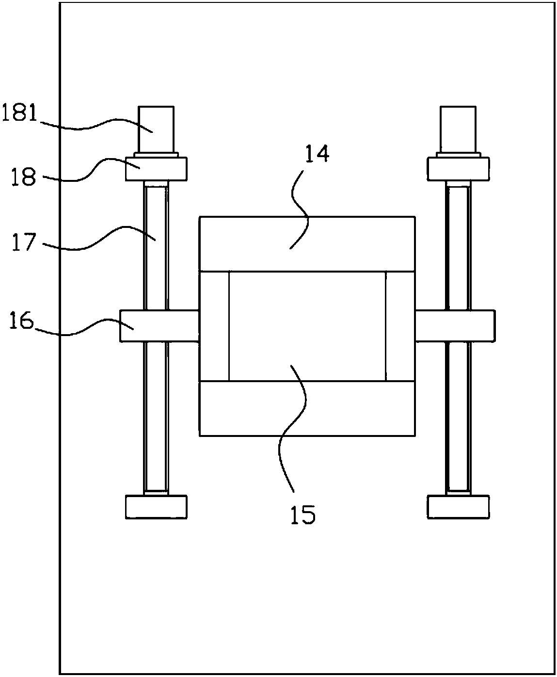
[0014] Example: see Figure 1 to Figure 2 As shown, a fixed moving mechanism for the side wall polishing mechanism of bending hardware includes a frame 10, the middle top surface of the top plate of the frame 10 is provided with a fixed block 15, and the middle part of the top surface of the fixed block 15 has a Groove 152, the installation groove that the bottom surface of groove 152 has is fixed with electromagnet plate 153, the workpiece 100 to be processed is adsorbed on the electromagnet plate 153, the bending portion that the both sides top surface of workpiece 100 to be processed has 101 is placed close to the inner side wall of the groove 152, the two sides of the fixed block 15 are fixed with the moving block 16, the moving block 16 is screwed in the horizontal screw rod 17, and the two ends of the horizontal screw rod 17 are hinged on the top of the top plate of the frame 10 On the corresponding support plate 18 that the front and the rear of both sides of the face a...


PUM


Abstract

The invention discloses a fixing and moving mechanism for a side wall polishing mechanism of bent hardware. The fixing and moving mechanism comprises a rack, a fixing block is arranged on the top faceof the middle of a top plate of the rack, and an upper placing groove is formed in the middle of the top face of the fixing block; an electromagnet plate is fixed in a mounting groove which is formedin the bottom face of the upper placing groove, a to-be-machined piece is attracted on the electromagnet plate, and bent parts arranged on the top faces of both sides of the to-be-machined piece areclosely attached to the inner side wall of the upper placing groove; moving blocks are fixed to the two sides of the fixing block and are in screwed connection with the interior of transverse screw rods; the two ends of the transverse screw rods are hinged to corresponding supporting plates which are fixed to the front part and the rear part of the two sides of the top face of the top plate of therack; driving motors are fixed on the rear wall face of the supporting plate at the rear; and output shafts of the driving motors are spline shafts, and the spline shafts are inserted into spline holes which are formed in one ends of the transverse screw rods in a sleeved mode. According to the fixing and moving mechanism for the side wall polishing mechanism of the bent hardware, the to-be-machined piece can be automatically fixed, the position of the to-be-machined piece can be moved, so that manual polishing or cooperation between manual polishing and automatic polishing mechanism of equipment is facilitated, and automatic polishing is facilitated accordingly.

Description

Technical field: [0001] The invention relates to the technical field of hardware component manufacturing equipment, and more specifically relates to a fixed moving mechanism for a side wall polishing mechanism of bending hardware. Background technique: [0002] After the existing mechanical parts are used for a certain period of time, they will be damaged or the surface will be rough and need to be polished regularly. Generally, the polishing of the plane is very convenient for manual polishing. However, when there are vertical bending parts on both sides of the mechanical parts, When the inner wall of the vertical bending part needs to be polished, manual polishing is very troublesome, and people need to move to polish different positions of the parts, and it is troublesome to clamp and fix such parts. Invention content: [0003] The purpose of the present invention is to address the deficiencies of the prior art, and to provide a fixed moving mechanism for the side wall ...

Claims


Application Information

Patent Timeline
Patent Type & Authority Applications(China)
IPC IPC(8): B24B29/02B24B41/06B24B41/02B24B55/00B24B47/06B24B27/00
Inventor 叶青
Owner FOSHAN RUIPUDA OPTOELECTRONICS TECH CO LTD
Learn More