Slag transfer device

A transfer device and slag technology, which is applied in the direction of transportation and packaging, mechanical conveyors, conveyors, etc., can solve the problems of flat trolley electrical equipment damage, power system damage, and insufficient slag bag capacity, so as to improve operating efficiency and improve The effect of reducing the amount of transshipment and operating costs

Active Publication Date: 2020-04-07
铜陵有色金属集团股份有限公司
View PDF6 Cites 0 Cited by
  • Summary
  • Abstract
  • Description
  • Claims
  • Application Information

AI Technical Summary

Problems solved by technology

This method of slag transfer has the following disadvantages: the splash that occurs during the slag dumping process makes the slag directly contact with the flat trolley, which may easily cause damage to the electrical equipment of the flat trolley; the power system of the electric flat trolley is easily affected by the high temperature of the slag contained Due to the limitation of the electric flat trolley, the capacity of the slag bag is insufficient, and multiple transfers are required to complete the discharge of the slag

Method used


Image

  • Slag transfer device
  • Slag transfer device
  • Slag transfer device

Examples


Embodiment Construction

[0013] The specific implementation of the present invention will be further described in detail below through the description of the embodiments in conjunction with the accompanying drawings.

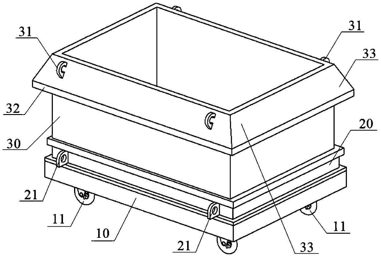
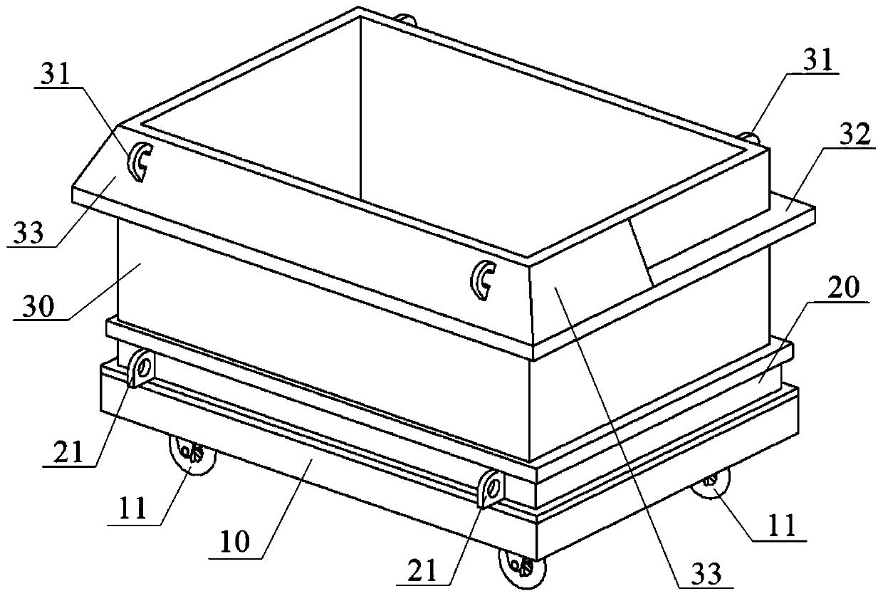
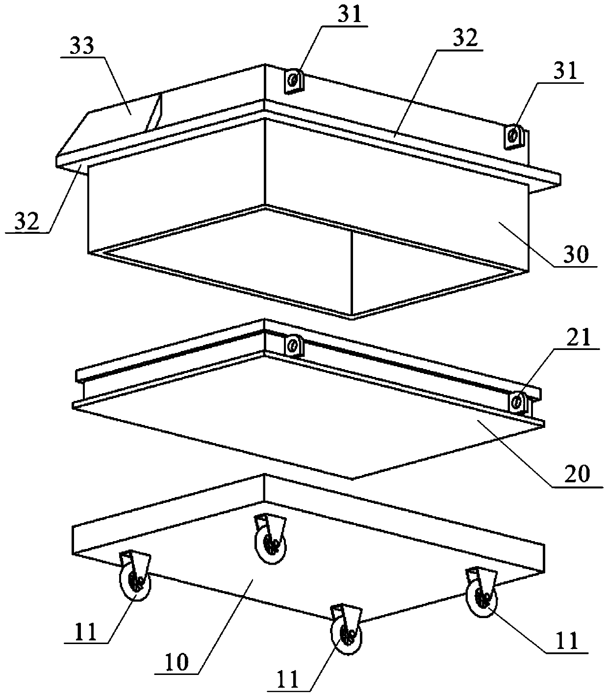
[0014] A slag transfer device, such as Figure 1-5 As shown, it includes a frame 10 and rollers 11 arranged below the frame 10. The frame 10 supports a pallet 20 and an enclosure frame 30, and the upper and lower open enclosure frames 30 are stacked on the pallet A cavity for holding slag is formed on 20. The pallet 20 constitutes the bottom of the cavity, and the surrounding frame 30 constitutes the peripheral side wall of the cavity. The pallet 20 and the enclosure frame 30 have a simple structure and are easy to clean, which can avoid the reduction of the slag capacity caused by the adhesion of slag to the slag, thereby improving the reuse rate of the pallet 20 and the enclosure frame 30.

[0015] When in use, the slag is poured into the cavity formed by the pallet 20 and the enclosure ...


PUM

PropertyMeasurementUnit
heightaaaaaaaaaa

Abstract

The invention belongs to the technical field of industrial furnace slag treatment, and particularly relates to a furnace slag transferring device. The furnace slag transferring device comprises a vehicle frame and roller wheels arranged under the vehicle frame. A carrying plate and a surrounding frame are supported on the vehicle frame. The surrounding frame with an upper opening and a lower opening is pressed on the carrying plate to form a containing cavity for containing furnace slag. When the furnace slag transferring device is used, the transferring device is only used for containing thefurnace slag, a power device is used for traction to realize conveying of the furnace slag, high-temperature damage to a power system is avoided, and the single-time transferring amount of the furnaceslag can be improved. The discharging operation efficiency of the furnace slag is improved, and the operation cost is effectively lowered.

Description

Technical field [0001] The invention belongs to the technical field of industrial slag processing, and particularly relates to a slag transfer device. Background technique [0002] In the prior art, the slag flows into the slag ladle through the slag hopper, and the slag ladle is placed on an electric flat trolley, and the electric flat trolley is guided along the track to the driving operation area, thereby realizing the transfer of the slag. This slag transfer method has the following shortcomings: the splashing during the slag dumping makes the slag and the trolley directly contact, which is easy to cause damage to the electrical equipment of the trolley; the power system of the electric trolley is easily affected by the high temperature of the slag contained in it. Due to the limitation of the electric flat trolley, the capacity of the slag bag is insufficient, and multiple transfers are required to complete the discharge of the slag. Summary of the invention [0003] The pur...

Claims


Application Information

Patent Timeline
Patent Type & Authority Patents(China)
IPC IPC(8): B65G35/00
Inventor 陈金球王显超汪文斌余小华席光耀邓印华宫志昊张彤纬杨年张文强
Owner 铜陵有色金属集团股份有限公司
Why Eureka
Try Eureka