
Switching control method for hybrid power sources of railway engineering machinery

A technology of power source switching and railway engineering, which is applied in the direction of traction driven by engines, transmissions driven by electric motors, electric vehicles, etc., to achieve the effect of improving work efficiency, expanding the scope of application, and reducing exhaust emissions.

Active Publication Date: 2018-01-23
ZHUZHOU TIMES ELECTRONICS TECH CO LTD +1
View PDF9 Cites 5 Cited by
  • Summary
  • Abstract
  • Description
  • Claims
  • Application Information

AI Technical Summary

Problems solved by technology

[0007] In view of this, the purpose of the present invention is to provide a control method for switching between hybrid power sources of railway construction machinery to solve the technical problem of ensuring that the operating mechanism can work continuously without impact when switching between the two power sources

Method used


Image

  • Switching control method for hybrid power sources of railway engineering machinery
  • Switching control method for hybrid power sources of railway engineering machinery
  • Switching control method for hybrid power sources of railway engineering machinery

Examples


Embodiment 1

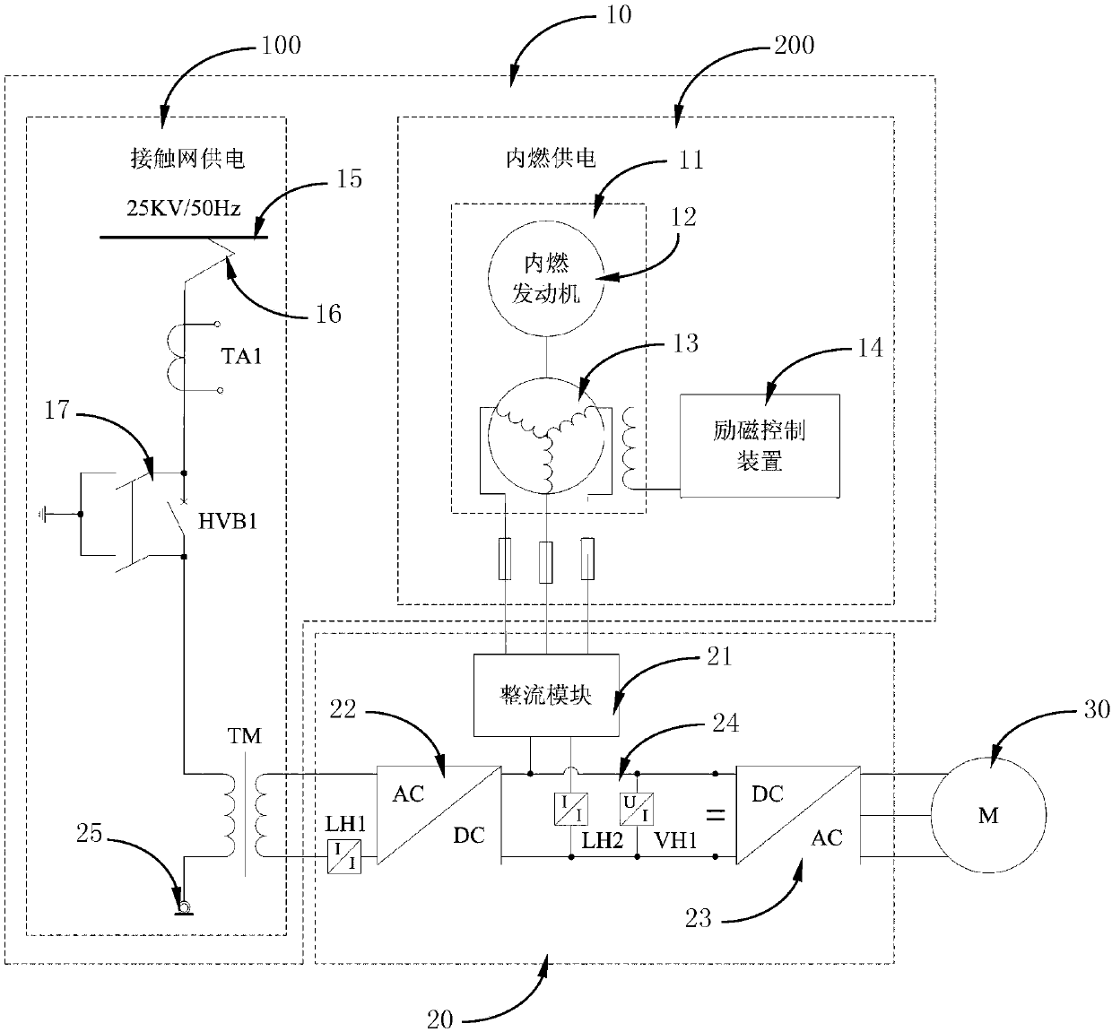
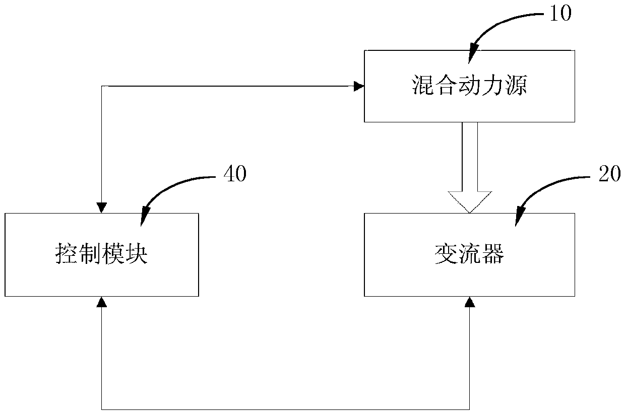
[0056] as attached figure 1 Shown, a specific embodiment of the railway engineering machinery hybrid power source switching system based on the method of the present invention, the system includes: a hybrid power source 10, and a converter 20 connected to the hybrid power source 10, the hybrid power source 10 The traction motor 30 is powered via the converter 20 . The hybrid power source 10 further includes an catenary power supply module 100 and an internal combustion power supply module 200 , and the electric energy from the catenary power supply module 100 or the internal combustion power supply module 200 is transformed and processed by the converter 20 and converted into electric energy required by the traction motor 30 . The railway construction machinery hybrid power source switching system described in this embodiment adopts the electric / internal combustion hybrid power main circuit, which includes two modes of catenary power supply and internal combustion generator se...

Embodiment 2

[0064] as attached Figure 4 As shown, a specific embodiment of a control method for switching a hybrid power source of railway engineering machinery. The hybrid power source 10 includes a catenary power supply module 100 and an internal combustion power supply module 200, and the electric energy from the catenary power supply module 100 or the internal combustion power supply module 200 is passed through The converter 20 converts and processes the electrical energy required by the traction motor 30 . The control method includes the following steps:

[0065] A) When the electrical connection between the railway engineering machinery 1 and the catenary 15 is turned on, and the catenary 15 continues to supply power, the traction motor 30 is powered by the catenary power supply module 100;

[0066] B) When the electrical connection between the railway engineering machinery 1 and the catenary 15 is disconnected, or the catenary 15 cannot continue to supply power, the internal com...

Embodiment 3

[0086] Another specific embodiment of a hybrid power source switching control method for railway engineering machinery. The hybrid power source 10 includes a catenary power supply module 100 and an internal combustion power supply module 200. The electric energy from the catenary power supply module 100 or the internal combustion power supply module 200 is converted. Converted and processed by the converter 20, it is converted into the electric energy required by the traction motor 30. The control method includes the following steps:

[0087] A) When the electrical connection between the railway engineering machinery 1 and the catenary 15 is turned on, and the catenary 15 continues to supply power, the traction motor 30 is powered by the catenary power supply module 100;

[0088] B) When the electrical connection between the railway engineering machinery 1 and the catenary 15 is disconnected, or the catenary 15 cannot continue to supply power, the internal combustion power sup...


PUM


Abstract

The invention discloses a switching control method for hybrid power sources of railway engineering machinery. The hybrid power sources comprise a catenary power supply module and an internal combustion power supply module, electrical power from the catenary power supply module or the internal combustion power supply module is converted and processed by a converter and then converted into electricpower required by a traction motor. When a catenary is electrically connected and power is continuously supplied to the catenary, the power is supplied to the traction motor through the catenary powersupply module. When the catenary is not electrically connected or power cannot be continuously supplied to the catenary, the power is supplied to the traction motor through the internal combustion power supply module. When the two power supply modules need to be switched, the catenary power supply module and the internal combustion power supply module supply the power to the traction motor at thesame time during switching, and the replaced power supply module stops supplying the power when switching is finished. The switching control method for the hybrid power sources of the railway engineering machinery can achieve the technical purpose that when the two power sources are switched, it is ensured that an operating mechanism can run continuously without impact.

Description

technical field [0001] The invention relates to the technical field of railway engineering machinery, in particular to a hybrid power source switching control method applied to railway engineering machinery. Background technique [0002] At present, my country's railway construction machinery is basically powered by internal combustion engines, and the transmission mode is hydraulic transmission. Long-term practice has proved that the internal combustion hydraulic (hydraulic) transmission mode is stable and reliable, and can meet the traction requirements of railway construction machinery. However, with the increasingly stringent environmental protection standards, the improvement of energy saving and emission reduction requirements, the requirements of high power and high speed and the development of clean power sources, this method shows complex maintenance, serious environmental pollution and noise pollution, low efficiency and limited driving ability. and other limitatio...

Claims


Application Information

Patent Timeline
Patent Type & Authority Applications(China)
IPC IPC(8): B60L11/02B60L9/00B61C9/38B60L50/10
CPCY02T10/70
Inventor 陈平松刘洁唐贵李懿梁兴元吴磊余高翔郭平肖晓芳钟大力曾海林肖小山
Owner ZHUZHOU TIMES ELECTRONICS TECH CO LTD
Learn More