A pull rod device for a syringe

The technology of a lever device and a syringe, which is applied to hypodermic injection devices and other directions, can solve the problems of uneven amount of injected medicinal liquid, unfavorable reading of medicinal liquid amount, easy to generate vibration, etc., and achieves stable and reliable structural connection, convenient self-destruction and disassembly, Stable and reliable structure

Active Publication Date: 2020-11-20
平邑县经发信息服务有限公司
View PDF14 Cites 0 Cited by
  • Summary
  • Abstract
  • Description
  • Claims
  • Application Information

AI Technical Summary

Problems solved by technology

[0003] Most of the existing disposable syringes add protective shields or sheaths, needle caps, sleeves, etc. for the needle near the needle. After the injection is completed, these accessories are used to cover the needle to prevent medical personnel from being stabbed. However, these The main body of the disposable syringe is not damaged, and it can still be used after recycling, which brings opportunities for criminals; there are also some disposable syringes with a sleeve outside the syringe. After use, the entire syringe, including the needle, retracts into the sleeve to prevent The needle hurts people, and at the same time, the various parts of the syringe are locked or stuck to realize the function of a safe syringe. However, adding a sleeve outside the syringe will cover the scale line of the syringe, which is not conducive to the operator to accurately read the amount of liquid medicine. The design of the lock shape is easy to generate vibration during use, resulting in uneven injection volume and bringing additional pain to patients

Method used


Image

  • A pull rod device for a syringe
  • A pull rod device for a syringe
  • A pull rod device for a syringe

Examples


Embodiment Construction

[0020] The following will clearly and completely describe the technical solutions in the embodiments of the present invention with reference to the accompanying drawings in the embodiments of the present invention. Obviously, the described embodiments are only some, not all, embodiments of the present invention. Based on the embodiments of the present invention, all other embodiments obtained by persons of ordinary skill in the art without making creative efforts belong to the protection scope of the present invention.

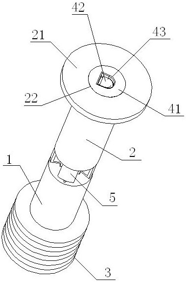
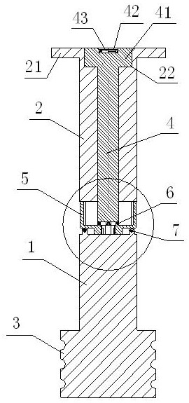
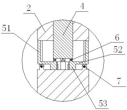
[0021] see Figure 1~3 , the present invention provides a technical solution: a pull rod device for syringes, including an upper rod body 2, a lower rod body 1 and a piston 3 arranged in sequence from top to bottom, and a rod body wing plate is extended on the top side wall of the upper rod body 2 21. The inside of the upper rod body 2 is provided with a hollow rod cavity, and an inner rod body 4 is inserted inside the hollow rod body. The rod cap sinking gro...


PUM


Abstract

The invention discloses a pull rod device for an injector. The pull rod device comprises an upper rod body, a lower rod body and a piston which are arranged from top to bottom in sequence, a hollow rod cavity is formed in the upper rod body in a through mode, an inner rod body is installed in the hollow rod cavity in an inserted mode, an inner rod cap is arranged on the top of the inner rod body,a rod cap sinking groove matched with the inner rod cap is formed in the top surface of the upper rod body, a hand-pull ring is connected onto the top surface of the inner rod cap in a hinged mode, multiple bent plates are distributed on the periphery of the bottom of the inner rod body, the upper end of the inner side of each bent plate is connected with the bottom of the inner rod body through afirst hinge, the lower end of the inner side of each bent plate is arranged on the top surface of the lower rod body in a contacted mode, the upper end of the outer side of each bent plate is fixedlyconnected with the bottom surface of the upper rod body in a bonded mode, and the lower end of the outer side of each bent plate is connected with the top surface of the lower rod body through a second hinge. According to the pull rod device for the injector, the structural design is reasonable, normal number reading is not affected, structural connection is stable and reliable, self-destroying dismounting is convenient, and the pull device is suitable of be used as a push-pull rod of the disposable injector.

Description

technical field [0001] The invention relates to the technical field of medical injection devices, in particular to a pull rod device for a syringe. Background technique [0002] A syringe is a common medical device. As early as the 15th century, the Italian Catinelle proposed the principle of the syringe. The gas or liquid is withdrawn or injected mainly with a needle. Syringes are also used in medical equipment, containers, and scientific instruments such as some chromatography to inject through a rubber septum. [0003] Most of the existing disposable syringes add protective shields or sheaths, needle caps, sleeves, etc. for the needle near the needle. After the injection is completed, these accessories are used to cover the needle to prevent medical personnel from being stabbed. However, these The main body of the disposable syringe is not damaged, and it can still be used after recycling, which brings opportunities for criminals; there are also some disposable syringe...

Claims


Application Information

Patent Timeline
Patent Type & Authority Patents(China)
IPC IPC(8): A61M5/50
Inventor 张艳霞
Owner 平邑县经发信息服务有限公司
Why Eureka
Try Eureka