
Air pressure measuring device and air pressure measuring method

An air pressure and measurement technology, which is applied in the direction of measuring device, elastic deformation gauge fluid pressure measurement, fluid pressure measurement, etc., can solve the problems of output saturation, film damage, large film deformation, etc.

Active Publication Date: 2020-04-10
MERRY ELECTRONICS (SUZHOU) CO LTD
View PDF6 Cites 0 Cited by
  • Summary
  • Abstract
  • Description
  • Claims
  • Application Information

AI Technical Summary

Problems solved by technology

However, if it is in an environment with large pressure changes, such as an aircraft, due to excessive pressure changes in a short period of time, it is easy to cause excessive deformation of the membrane, resulting in output saturation or even membrane damage.

Method used


Image

  • Air pressure measuring device and air pressure measuring method
  • Air pressure measuring device and air pressure measuring method
  • Air pressure measuring device and air pressure measuring method

Examples


Embodiment 1

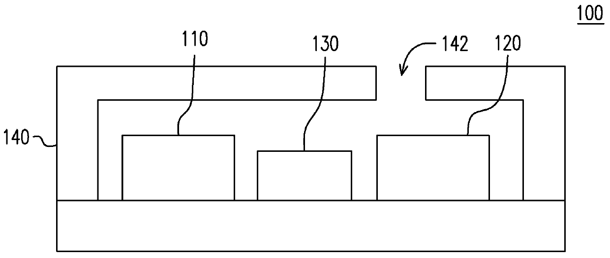
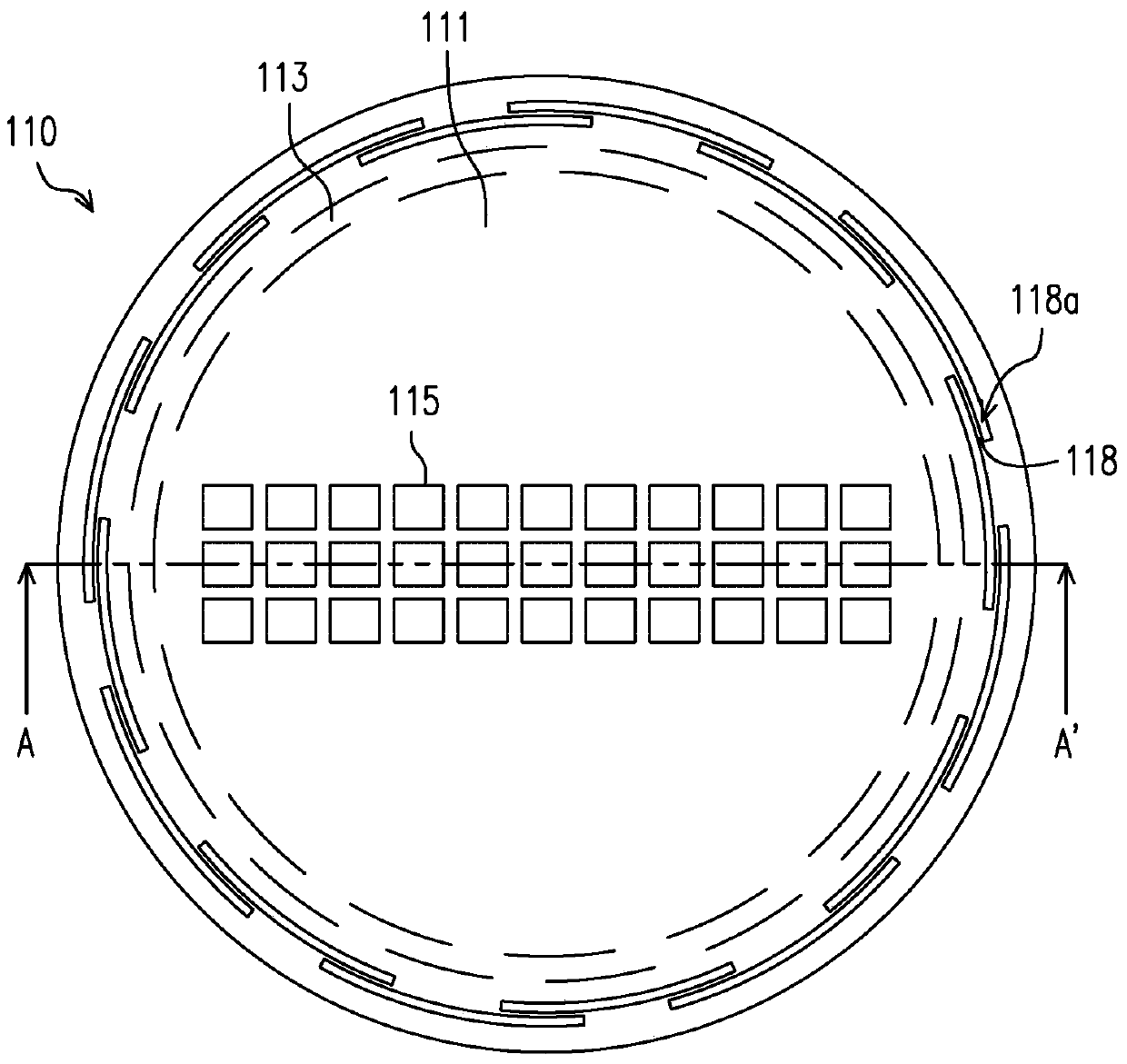
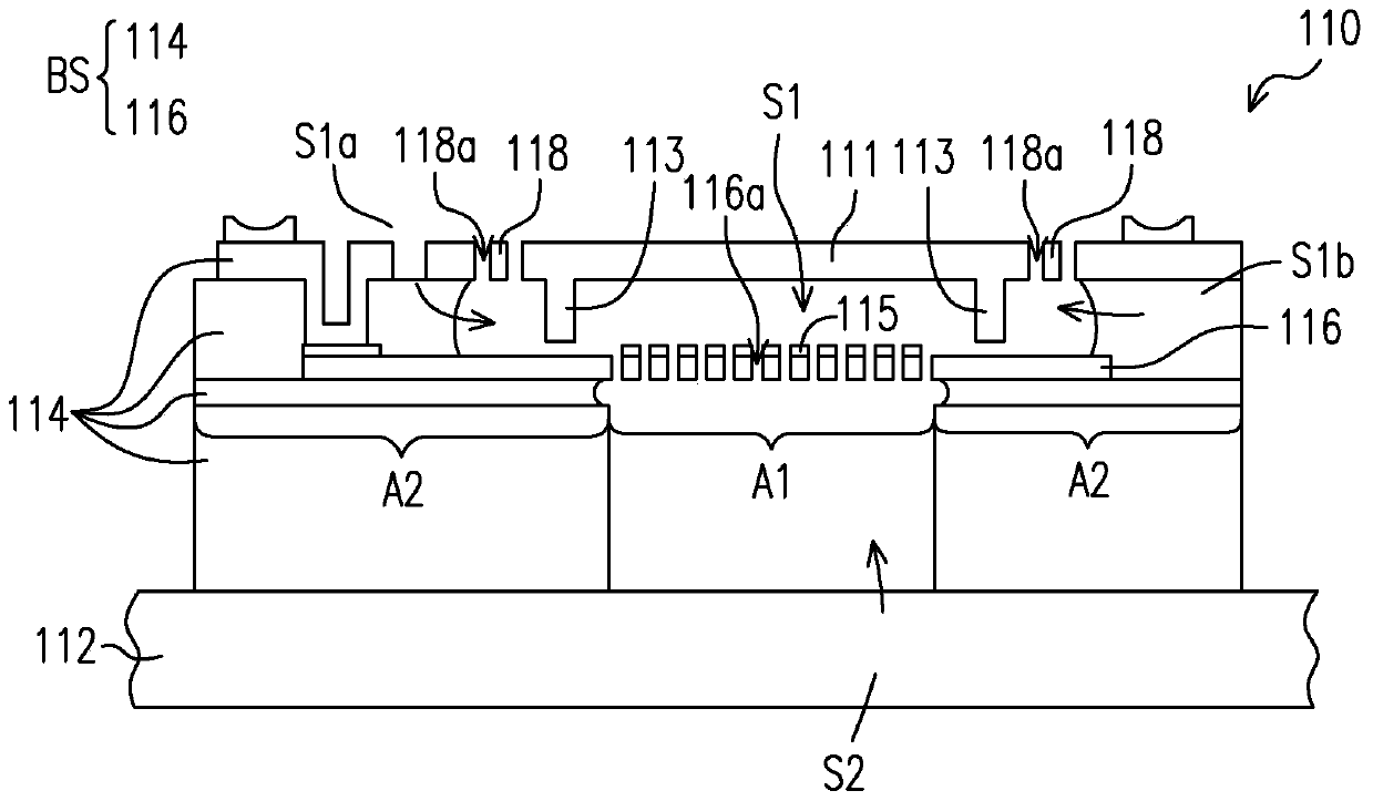
[0076] Embodiment one: see attached Figure 1-4 As shown, in this embodiment, the air pressure measurement device 100 includes a housing 140 and a first sensing unit 110, a second sensing unit 120 and a control module 130 disposed in the housing, wherein the control module 130 includes a special application A functional module composed of an integrated circuit (Application-specific integrated circuit, ASIC) or other components with similar functions is electrically connected to the first sensing unit 110 and the second sensing unit 120 . The first sensing unit 110 may be a capacitive pressure sensor made with MEMS technology, and the second sensing unit 120 may be a piezoresistive pressure sensor.

[0077] In this embodiment, the measurement accuracy of the first sensing unit 110 is greater than the measurement accuracy of the second sensing unit 120 , and the measurement range of the second sensing unit 120 is greater than the measurement range of the first sensing unit 110 ...

Embodiment 2

[0088] Embodiment two: see attached Figure 8-9 As shown, the present embodiment is basically the same as the first embodiment, except that in the first sensing unit 210 of the present embodiment, the support member 213 is integrated with the semiconductor layer 216 of the semiconductor layer structure.

[0089] Further, the first sensing unit 210 is adapted to be disposed on the circuit substrate 212 , and the first sensing unit 210 includes a semiconductor layer structure (including a plurality of semiconductor layers 214 and 216 ), a thin film 211 and an elastic member 218 . Similar to the foregoing embodiments, the semiconductor layer structure has a cavity, and the film 211 is connected to the semiconductor layer 214 via an elastic member 218 to be movably suspended in the cavity, and the semiconductor layer 216 is provided with a plurality of electrodes 215 facing the film 211, And with the control module 130 (as attached figure 1 , attached Image 6 shown, omitted in ...


PUM


Abstract

The invention discloses an atmospheric pressure measurement device that includes a first sensing unit and a second sensing unit. The first sensing unit includes a semiconductor layer structure, a film, and a support. The semiconductor layer structure has a cavity to communicate with external environment. The film is movably and deformably configured in the semiconductor layer structure and suspended in the cavity. The support is disposed between the semiconductor layer structure and the film. Electrostatic force is configured to be arranged between the semiconductor layer structure and the film to drive the film such that a part of the semiconductor layer structure, the support and the film come into contact and define a closed space in the cavity. The film is separated between the external environment and the closed space, and deforms due to a difference in atmospheric pressure between the external environment and the closed space. An atmospheric pressure measurement method is also provided.

Description

technical field [0001] The invention relates to an air pressure measuring device and an air pressure measuring method. Background technique [0002] Miniature pressure gauges made with micro-electromechanical technology have been widely used in consumer electronics, automotive electronics, medical electronics, and industrial electronics. However, the products are used in various environments. For a single type of air pressure measuring device, when the product is used in a widely different environment, it is often limited by the sensing range or sensing accuracy of the pressure gauge. , but cannot accurately measure the pressure in the environment or cause failure due to excessive pressure changes. [0003] For example, for a pressure gauge with high measurement accuracy, it usually obtains an accurate pressure value through the slight deformation of the membrane structure. However, if it is in an environment with large pressure changes, such as an aircraft, due to the lar...

Claims


Application Information

Patent Timeline
Patent Type & Authority Patents(China)
IPC IPC(8): G01L7/08G01L9/00
Inventor 陈振颐王俊杰张朝森张咏翔
Owner MERRY ELECTRONICS (SUZHOU) CO LTD
Learn More