
Sewage treatment process with convenient automatic operation

A technology for sewage treatment and automatic operation, which is applied in water/sewage multi-stage treatment, water/sludge/sewage treatment, water pollutants, etc., and can solve the problem of inconvenient bottom sludge replacement.

Inactive Publication Date: 2018-01-19
钟益洁
View PDF0 Cites 0 Cited by
  • Summary
  • Abstract
  • Description
  • Claims
  • Application Information

AI Technical Summary

Problems solved by technology

[0005] The purpose of the present invention is to provide a sewage treatment process that is easy to operate automatically, so as to solve the problem that the existing sewage treatment device is inconvenient to replace the bottom sludge, and at the same time, the present invention can realize automatic operation

Method used


Image

  • Sewage treatment process with convenient automatic operation

Examples


Embodiment 1

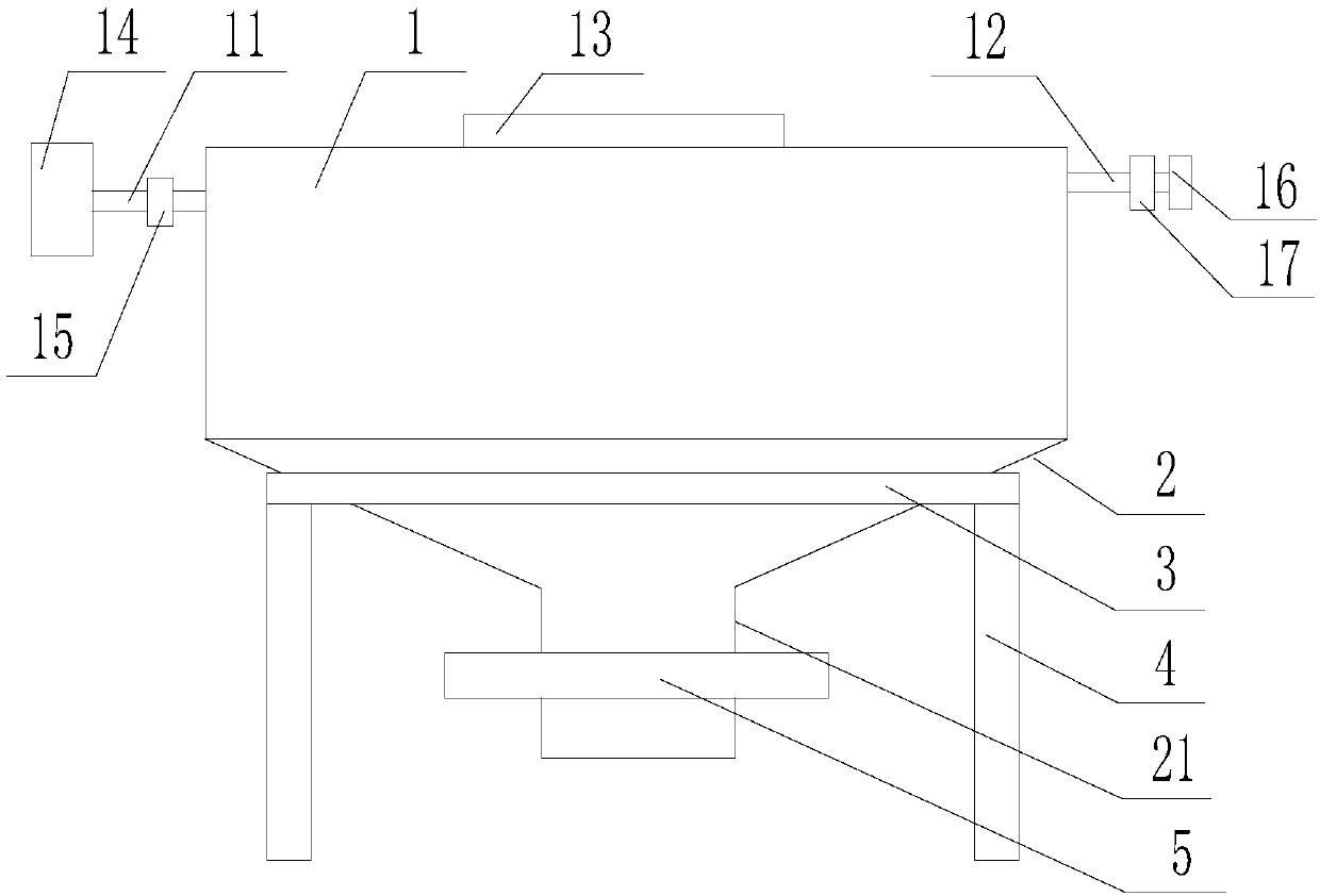
[0037] Such as figure 1 As shown, the sewage treatment process that is convenient for automatic operation includes the following steps:

[0038] 1) Centralized collection of sewage;

[0039] 2) transporting the sewage collected in step 1) to the sedimentation tank for sewage precipitation;

[0040] 3), transporting the settled sewage in step 2) to the sludge tank for organic matter treatment,

[0041] 4), transporting the sewage treated in step 3) to the membrane tank for membrane filtration treatment;

[0042] 5) Discharge after passing the water quality test;

[0043] Described settling tank comprises tank body 1, and described tank body 1 is provided with inlet pipe 11 and outlet pipe 12, and described inlet pipe 11 is provided with inlet valve 15, and described outlet pipe 12 is provided with outlet valve 16, The bottom of the tank body 1 is provided with sludge, and the bottom of the tank body 1 is sunken downward to form an arc-shaped groove 2, and the bottom of the ...

Embodiment 2

[0045] Such as figure 1 As shown, this embodiment is based on Embodiment 1, the top of the tank body 1 is provided with a dosing tube 13; the tank body 1 is arranged in an annular support body 3 supported by three legs 4 The mud discharge pipe 21 is suspended in the air; the water inlet pipe 11 is provided with a filter 14 at the front end of the water inlet valve 15; the outlet pipe 12 is provided with a sewage online detector 17 at the front end of the water outlet valve 16.

[0046] Example 2:

[0047] The present embodiment is based on embodiment 1 or embodiment 2, in step 1) adds sewage treatment agent, and described sewage treatment agent is made up of following components by weight:

[0048] 30 parts by weight of polyacrylamide, 15 parts by weight of basic aluminum chloride, 10 parts by weight of ferric oxide, 25 parts by weight of calcium oxide, and 15 parts by weight of bentonite.

[0049] In this embodiment, the polyacrylamide described in the present invention has...


PUM


Abstract

The invention discloses a sewage treatment process with convenient automatic operation. The process comprises the following steps: 1) carrying out centralized collection on sewage; 2) conveying collected sewage into a precipitation tank for precipitation; 3) conveying the sewage to a sludge tank for treatment; 4) then, carrying out membrane filtration treatment; 5) discharging water after water quality is qualified by detection. The sedimentation tank comprises a tank body, wherein a water inlet pipe and a water outlet pipe are arranged on the tank body, a water inlet valve is arranged on thewater inlet pipe, a water outlet valve is arranged on the water outlet pipe, sludge is arranged at the bottom of the tank body, the bottom of the tank body is downwards dented to form an arc-shaped groove, a sludge discharge pipe is arranged at the bottom of the arc-shaped groove, and an electromagnetic valve is arranged on the sludge discharge pipe. The sedimentation tank further comprises a controller, wherein the controller is in communication connection with the water inlet valve, the water outlet valve and the electromagnetic valve, and the tank body is provided with a liquid level sensorin communication connection with the controller. According to the process, the problem of the existing sewage treatment devices that the sludge at the bottom is inconvenient to replace is solved, andmeanwhile, automated operation can be achieved.

Description

technical field [0001] The invention relates to the technical field of sewage treatment, in particular to a sewage treatment process that is convenient for automatic operation. Background technique [0002] Technology is developing, society is progressing, and people's living standards are constantly improving, but the accompanying environmental pollution is also becoming more and more serious. Environmental pollution mainly includes air pollution, sudden pollution and water pollution. [0003] Water pollution mainly includes industrial pollution and domestic sewage. Among them, industrial pollution is particularly serious. How to solve water pollution has become an urgent problem. [0004] The existing sewage treatment device is mainly for sludge treatment, and the sludge needs to be replaced after a long time of use. The existing sewage treatment device is not convenient for replacing the bottom sludge. Contents of the invention [0005] The purpose of the present inve...

Claims


Application Information

Patent Timeline
IPC IPC(8): C02F9/04C02F101/30
Inventor 钟益洁
Owner 钟益洁
Learn More