Control method of visual fixation lamp used for fundus imaging instrument

A lamp control and imager technology, applied in the field of fixation lamp control, can solve the problems of easy operation errors, unfavorable medical personnel to control the fixation lamp at the same time, etc., and achieve the effect of simple operation and concise control interface

Inactive Publication Date: 2018-01-19
SUZHOU MICROCLEAR MEDICAL INSTR
View PDF8 Cites 0 Cited by
  • Summary
  • Abstract
  • Description
  • Claims
  • Application Information

AI Technical Summary

Problems solved by technology

The existing fundus imager controls the opening and closing of the fixation lamp through mechanical buttons. This control method is not conducive to the medical staff to control the corresponding software while controlling the fixation lamp.
Moreover, when the number of fixation lamps is large, it is easy to make operation errors

Method used


Image

  • Control method of visual fixation lamp used for fundus imaging instrument
  • Control method of visual fixation lamp used for fundus imaging instrument
  • Control method of visual fixation lamp used for fundus imaging instrument

Examples


Embodiment Construction

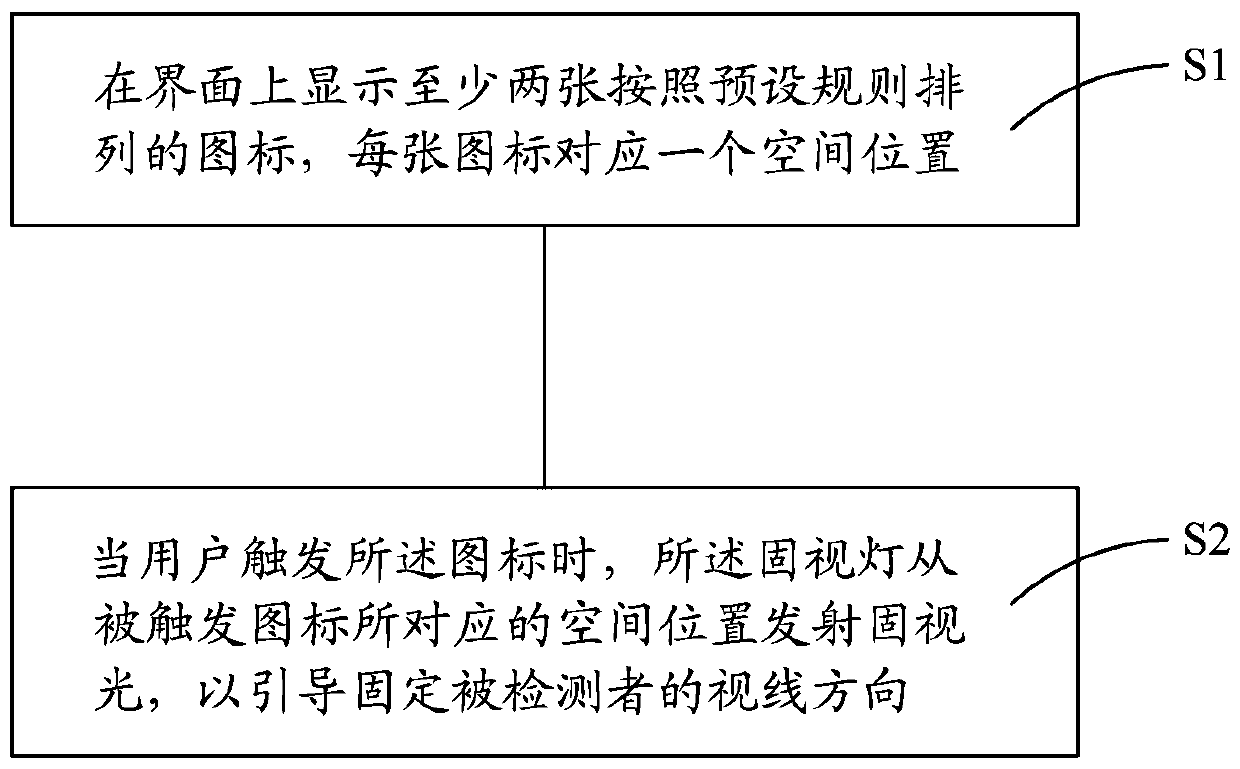
[0020] see figure 1 As shown, the present invention is used for the fixation lamp control method of fundus imager and comprises steps:

[0021] S1: Display at least two icons arranged according to preset rules on the interface, and each icon corresponds to a spatial position.

[0022] Specifically, the interface may be a display screen, or a software operation interface. The preset rule is the arrangement of the icons, for example, the icons can be photographed in a row or a column or a circle or a square or a regular polygon. The spatial position is the light-emitting position of the fixation lamp.

[0023] S2: When the user triggers the icon, the fixation light emits fixation light from the spatial position corresponding to the triggered icon, so as to guide the method of fixing the line of sight of the detected person.

[0024] Specifically, the trigger may be that the mouse stays on the icon, or the mouse clicks or double-clicks on the icon, or the user's finger clicks ...


PUM


Abstract

The invention discloses a control method of a visual fixation lamp used for a fundus imaging instrument. The method comprises the following steps: displaying at least two icons on an interface, wherein the at least two icons are arrayed according to a pre-set rule with each icon corresponding to one spatial position; when a user triggers icons, emitting visual fixation light from spatial positionscorresponding to triggered icons by the visual fixation lamp in order to guide and fix the visual direction of a testee. Compared with the prior art, the control method of the visual fixation lamp used for the fundus imaging instrument is easy and convenient to operate and has a concise control interface.

Description

technical field [0001] The invention relates to a method for controlling a fixation lamp of a fundus imager. Background technique [0002] The fundus imager belongs to the field of medical imaging and is used to obtain images of the retina of the fundus so that medical personnel can check fundus diseases or assist medical personnel to judge the condition of other organs. However, due to the limitation of the pupil size of the human eye, only a fundus image range of about 30 to 40 degrees of viewing angle can be captured. Therefore, in order to observe the fundus image of a specific region of the patient, the patient is usually required to fix the line of sight in a specific direction so as to display the specific region. However, in a dark room, it is difficult for people to fix the direction of the eyeball for a long time. Therefore, it is necessary to fix the patient's line of sight direction by means of a fixation light. The existing fundus imager uses mechanical butto...

Claims


Application Information

Patent Timeline
IPC IPC(8): A61B3/12A61B3/14A61B3/00
Inventor 牛海涛李超宏赵恩毅邱伟陈晓梅李磊朱嵬鹏管鹏程
Owner SUZHOU MICROCLEAR MEDICAL INSTR
Why Eureka
Try Eureka