Controller diagnosis signal generation, fault protection and function safety method and system
A controller and signal technology, applied in the field of control, can solve the problems of lack of versatility, inability to find out in time, time-consuming and other problems, and achieve the effect of easy detection and high reliability
- Summary
- Abstract
- Description
- Claims
- Application Information
AI Technical Summary
Problems solved by technology
Method used
Image
Examples
Embodiment 1
[0143] This embodiment provides a method for generating a controller diagnostic signal. The controller in this embodiment may be a controller in a control system configured with a single controller, or a redundant controller in a redundant control system ( The controllers in the redundant control system are called redundant controllers).
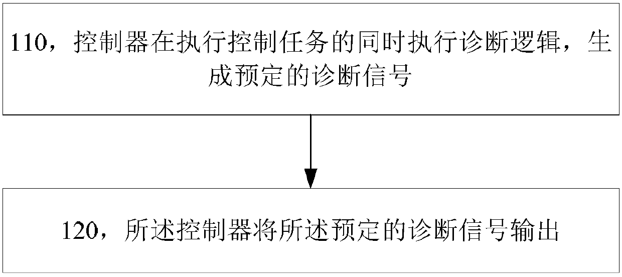
[0144] Such as figure 1 As shown, the method of this embodiment includes:
[0145] Step 110, the controller executes the diagnostic logic while executing the control task, and generates a predetermined diagnostic signal;
[0146] In this embodiment, the diagnostic logic includes digital signal inversion logic, and the predetermined diagnostic signal is a pulse train signal. Optionally, the duty ratio of the pulse train signal is 1, and the pulse width is equal to the control cycle of the controller. This kind of diagnostic signal is convenient for the controller to generate, and when the controller fails to perform the control task, the d...
Embodiment 2
[0169] This embodiment provides a controller failure protection method. Similar to Embodiment 1, the controller in this embodiment may be a controller in a control system configured with a single controller, or a redundant controller in a redundant control system.
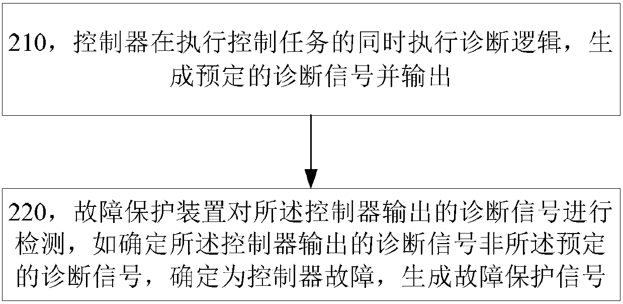
[0170] Such as image 3 As shown, the method of this embodiment includes:
[0171] Step 210, the controller executes the diagnostic logic while executing the control task, generates and outputs a predetermined diagnostic signal;
[0172] In this embodiment, the predetermined diagnostic signal is a pulse train signal, the duration of the high level of the pulse train signal is T1, and the duration of the low level is T2; optionally, the duty of the pulse train signal The ratio is 1, T1=T2=T, and T is the control cycle of the controller.
[0173] In this embodiment, the diagnostic signal output by the controller includes a first pulse train signal and a second pulse train signal with opposite phases; or, the diagn...
Embodiment 3
[0217] This embodiment provides a fault protection device for diagnosing a diagnostic signal that is normally a pulse train signal. Its function is consistent with that of the fault protection device in Embodiment 1, but this embodiment mainly describes its own structure, as Figure 5 As shown, the fault protection device includes:
[0218] The first detection circuit 401 includes a first switch unit connected in series and a first delay action unit, and the first delay action unit is configured when the turn-on time of the first switch unit reaches a preset first delay time action;
[0219] The second detection circuit 402 includes a second switch unit connected in series and a second delay action unit, and the second delay action unit acts when the turn-on time of the second switch unit reaches a preset second delay time ;
[0220] The signal generation circuit 403 generates a failsafe signal when detecting that any one of the first delay action unit and the second delay a...
PUM
 Abstract
Description
Claims
Application Information
 - Generate Ideas
- Intellectual Property
- Life Sciences
- Materials
- Tech Scout
- Unparalleled Data Quality
- Higher Quality Content
- 60% Fewer Hallucinations
Browse by: Latest US Patents, China's latest patents, Technical Efficacy Thesaurus, Application Domain, Technology Topic, Popular Technical Reports.
© 2025 PatSnap. All rights reserved.Legal|Privacy policy|Modern Slavery Act Transparency Statement|Sitemap|About US| Contact US: help@patsnap.com


