A shield type TBM segment backfill grouting expansion type sealing device and construction method

A technology of backfill grouting and sealing device, which is applied in vertical shaft equipment, earthwork drilling, wellbore lining, etc., can solve the problems of segment support force exerting influence on backfill quality, bean gravel stuck to shield, untimely backfill, etc. Guarantee the effect of backfill quality and segment support force, efficient construction and safe construction

Active Publication Date: 2018-10-30
CHINA INST OF WATER RESOURCES & HYDROPOWER RES
View PDF6 Cites 0 Cited by
  • Summary
  • Abstract
  • Description
  • Claims
  • Application Information

AI Technical Summary

Problems solved by technology

Due to the tapered design of the shield-type TBM shield in actual engineering, the gap between the tail shield and the segment is small, the gap between the shield and the surrounding rock, and between the segment and the surrounding rock is large, and the segment and the shield There are no bean-gravel and mortar barrier components that are prone to the following disadvantages: (1) There are no bean-gravel and mortar barrier components. The bean-gravel and mortar are in the natural blow-fill and filling modes respectively, and it is easy to form backfill cavities at the top of the cave. (2) When the distance between the backfill part and the shield is small, the pea gravel and mortar enter the gap between the shield and the surrounding rock, and the cement grout is easy to cement the shield, while the bean gravel is easy to get stuck (3) When the distance between the backfill part and the shield is large, the backfill is not timely, and it is easy to cause the unsupported section of the surrounding rock to be too long, the deformation is too large, and the TBM equipment is locked.

Method used


Image

  • A shield type TBM segment backfill grouting expansion type sealing device and construction method
  • A shield type TBM segment backfill grouting expansion type sealing device and construction method
  • A shield type TBM segment backfill grouting expansion type sealing device and construction method

Examples


Embodiment 1

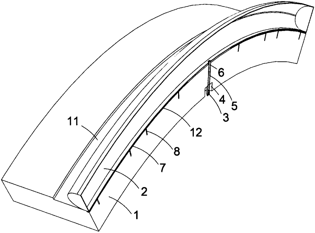
[0031] A shield-type TBM segment backfill grouting expansion type closure device, including segment 1, rubber bladder 2, air valve 3, segment valve hole 4, inflation tube extension tube 5, rubber bladder inflation tube 6, rubber bladder fixing strip 7. Anchor bolts for rubber bladder fixing strips 8, rubber bladder fixing sleeves 9, segment inflation tube holes 10, rubber bladder installation grooves 11, rubber bladder fixing strip installation grooves 12; rubber bladder installation grooves 11 are set on the outer peripheral surface of segment 1 Above, the installation groove 12 of the rubber bladder fixing strip is set in the rubber bladder installation groove 11, the rubber bladder fixing strip 7 is installed in the rubber bladder fixing strip installation groove 12 through the rubber bladder fixing strip anchor bolt 8, and the rubber bladder fixing sleeve 9 is located on the rubber bladder 2, the rubber bag 2 is fixed on the rubber bag fixing bar 7 through the rubber bag fi...

Embodiment 2

[0040]A shield-type TBM segment backfill grouting expansion type closure device, including segment 1, rubber bladder 2, air valve 3, segment valve hole 4, inflation tube extension tube 5, rubber bladder inflation tube 6, rubber bladder fixing strip 7. Anchor bolts for rubber bladder fixing strips 8, rubber bladder fixing sleeves 9, segment inflation tube holes 10, rubber bladder installation grooves 11, rubber bladder fixing strip installation grooves 12; rubber bladder installation grooves 11 are set on the outer peripheral surface of segment 1 Above, the installation groove 12 of the rubber bladder fixing strip is set in the rubber bladder installation groove 11, the rubber bladder fixing strip 7 is installed in the rubber bladder fixing strip installation groove 12 through the rubber bladder fixing strip anchor bolt 8, and the rubber bladder fixing sleeve 9 is located on the rubber bladder 2, the rubber bag 2 is fixed on the rubber bag fixing bar 7 through the rubber bag fix...

Embodiment 3

[0049] A shield-type TBM segment backfill grouting expansion type closure device, including segment 1, rubber bladder 2, air valve 3, segment valve hole 4, inflation tube extension tube 5, rubber bladder inflation tube 6, rubber bladder fixing strip 7. Anchor bolts for rubber bladder fixing strips 8, rubber bladder fixing sleeves 9, segment inflation tube holes 10, rubber bladder installation grooves 11, rubber bladder fixing strip installation grooves 12; rubber bladder installation grooves 11 are set on the outer peripheral surface of segment 1 Above, the installation groove 12 of the rubber bladder fixing strip is set in the rubber bladder installation groove 11, the rubber bladder fixing strip 7 is installed in the rubber bladder fixing strip installation groove 12 through the rubber bladder fixing strip anchor bolt 8, and the rubber bladder fixing sleeve 9 is located on the rubber bladder 2, the rubber bag 2 is fixed on the rubber bag fixing bar 7 through the rubber bag fi...


PUM


Abstract

The invention discloses a backfill grouting expansion type sealing device of a shield type tunnel boring machine (TBM) segment and a construction method. The sealing device involves a rubber capsule and a fixed facility thereof, an air filling and exhaust port, a rubber capsule installation groove structure and construction steps, wherein the rubber capsule is fixed to the interior of a rubber capsule installation groove by virtue of a rubber capsule fixing strip, and the size and length of the rubber capsule can be adjusted as required; a segment filling tube hole, a segment valve hole, the rubber capsule installation groove and a rubber capsule fixing strip installation groove can be prefabricated or formed at a later stage, and the sizes can be adjusted according the size between the segment and surrounding rocks; and the construction steps comprise forming of the segment filling tube hole, the segment valve hole, the rubber capsule installation groove and the rubber capsule fixingstrip installation groove, installation, air exhaust and filling of the rubber capsule and the like. According to the backfill grouting expansion type sealing device, gaps between the shield type TBMsegment and the surrounding rocks can be quickly and effectively sealed, so that the blocking and sealing requirements of backfill grouting are satisfied.

Description

technical field [0001] The invention relates to the field of underground engineering construction, in particular to an external grouting sealing device for tunnel excavation segments and a construction method. Background technique [0002] The shield-type TBM advances with the excavation face during the excavation process, and establishes a connection between the surrounding rock and the segment lining through the bean gravel and mortar backfilling process, so as to achieve the purpose of the segment providing the supporting force of the surrounding rock. Due to the tapered design of the shield-type TBM shield in actual engineering, the gap between the tail shield and the segment is small, the gap between the shield and the surrounding rock, and between the segment and the surrounding rock is large, and the segment and the shield There are no bean-gravel and mortar barrier components that are prone to the following disadvantages: (1) There are no bean-gravel and mortar barri...

Claims


Application Information

Patent Timeline
Patent Type & Authority Patents(China)
IPC IPC(8): E21D11/10
Inventor 汪小刚刘立鹏孙兴松傅睿智皮进
Owner CHINA INST OF WATER RESOURCES & HYDROPOWER RES
Why Eureka
Try Eureka